}
Power Circuit Breakers Types AK-2 -15 and AK-2/3 -2 5 GEI - 50299
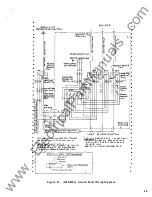
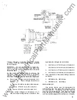
between them. See drawing 138B2454 (Figure
22) with the breaker restored to service with
the ground fault detector deactivated, establish
whether there is false tripping due to over
current.
FALSE TRIPPING CAUSED BY FAULTY GROUND
FAULT DETECTION
If the breaker is equipped for four wire service
(fourth C .T. remotely mounted, Figure 18) it is
important that the shielding be effective by having
continuity from the disconnect plug at the Power
Sensor Unit to the external
c.
T. and further, that
this shield be isolated from the signal conductors.
It
is also important that continuity exists through
the ground signal circuit. Check these conditions
as follows; referring to Figure 22 .
1. Remove connection plug at Power Sensor Unit
and check continuity between A and C (Signal).
Letters are located on end of plug.
1
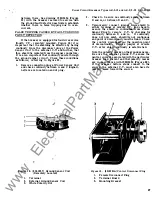
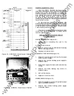
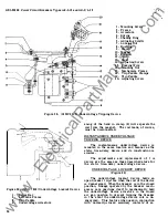
Figure 18. (804 1867) Ground Sensor Coil
(Remotely Located)
1 . Terminal
2. External Ground Sensor Coil
3 . White Polarity Dot
2 . Check to be sure no continuity exists between
R and
A,
or between R and C .
3 . Temporarily connect jumper from shield to
either terminal at remote C .T. and check to
assure the shield is continuous from Power
Sensor Plug to remote C. T. by checking for
continuity between R and A . If continuity
does not now exist, shield is not continuous
and point
of
discontinuity must be found. Check
the control disconnect as the possible point
of discontinuity. Remove jumper at remote
C . T. after shield continuity is established.
Note the polarity marks on the ground sensors.
Be sure the external ground C . T. senses the
neutral current associated with the particular
breaker load current and that polarity marks
are in accordance with 138B2454 (Figure 22).
If the breaker bottom studs connect to the
source, the external C .T. must also have its
polarity mark toward the source.
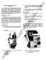
Figure 19 . (89183 80A) Control Disconnect Plug
1. Female Disconnect Plug
2 . Terminal Board
3.
Mounting Bracket
27
www
. ElectricalPartManuals
. com

