AK-3-25
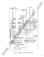
POWER SENSOR TRI P CABLING
r - - - - - - - - - - - - - - ,
r - - - - - - - - - - --,
BACK FRAME
1
1
POWER SUPPLY
I
MAGNETIC SENSORS
I
'
UNIT
I
I
I J
I
I
I
�gr� IA j
I
I
I
I
TEST
'- - - - - - - - - - - - _j
L - - - - - - - - - - J
r - - - - - - - - - - - - ,
I
L l
'
I
POWER SENSOR 1
UNIT
1
I
I
1
I
L - - - - - - - - - - - --'
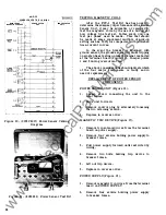
Figure 20. (0133C9017) Power Sensor Cabling
Diagram
2 8
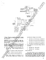
Figure 2 1 . (803 9962) Power Sensor Test Kit
TESTING MAGNETIC COILS
After the PST- 1 Test Kit has been used to
determine the adequacy of performance of the Power
Sensor Unit, it may be advisable or required to
test the magnetic coils by the use of a hi-current
Low voltage type test set.
In
this event, only one
test per phase need be made. This test should
be made at some convenient multiple of pick-up
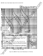
setting such as 3 00% for comparison with published
time-current curves.
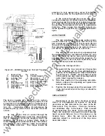
In the event the breaker is equipped with
ground sensor, the ground sensor will cause tripping
on single phase testing unless the signal is shorted
at the terminal board (Figure 22). Jumper points
1 and 5 during overcurrent test.
The above considerations should indicate which
of the four major components is faulty and in
need of replacement .
REPLACE MENT OF POWER SENSOR
COMPONENTS
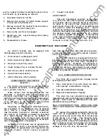
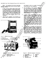
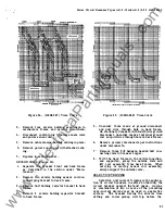
POWER SENSOR UNIT (Figure 1 6) .
1 . Loosen screw connecting the unit to the
front frame.
2 . Slide unit forward.
3 . Remove control plug by alternately loosening
the two retaining screws.
4.
Replace in reverse order.
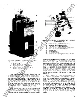
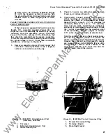
MAGNETIC TRIP DEVICE (Figure 17).
1.
Remove trip solenoid wires from the terminal
board on power supply.
2 .
Remove four screws holding power supply to
breaker frame .
3. Pull power supply forward until restricted by
wiring.
4 . Remove two bolts holding trip device to
breaker frame.
5. Lift out trip device.
6.
Replace in reverse order.
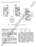
POWER SUPPLY (Figure 1 5).
1 . Remove magnetic trip wires from the terminal
board on POWER SUPPLY
2.
Remove four screws holding power supply
to breaker frame.
www
. ElectricalPartManuals
. com

