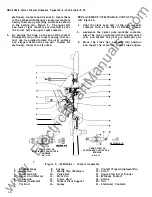
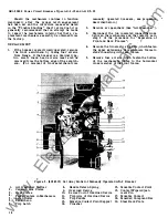


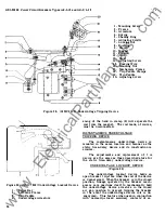

may be replaced without removing the device from
the breaker by proceeding as follows :
1.
Disconnect leads of coil (8).
2. Remove two screws (6) which fasten magnet
(7) and coil to the frame (2 ).
3. Having removed the magnet from the device,
straighten the end of clamp ( 9).
4.
Remove the coil from the magnet.
5. Install new coil, again forming end of clamp
(9) as shown.
6. Reassemble to frame.
7.
Connect coil leads.
ADJUSTMENT
The only adjustment required on the shunt
trip device is that which ensures positively that
the breaker will trip when the device is activated.
In order to be sure of this, armature arm (11)
must travel from 1/32 to 1/16 of an inch beyond
the point at which the breaker trips.
A good
method of checking this is to hold a 1/32nd shim
between the magnet and armature at (10) and with
the breaker closed, push upwards at (5
�
, closing
the armature against the magnet.
If
the breaker
trips, there is sufficient overtravel.
If
adjustment
is necessary, trip paddle (12 ) may be formed
towards or away from armature arm (11).
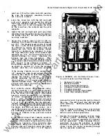
PROTECTIVE DEVICES
An AK-2/3 breaker may be equipped with
the following protective devices :
1 . Overcurrent trip (Magnetic) AK-2
2 . Power Sensor Trip (Static) AK-3
3 . Reverse Current Trip AK-2
4.
Under Voltage Trip
&
Lockout Device
5.
B ell Alarm and/or Lockout device
6. Open Fuse lockout device.
7.
AKD- 5 Interlock AK-2A/ AK-3A
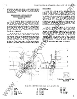
OVERCURRENT TRIP DEVICE
(Magnetic )
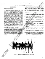
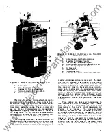
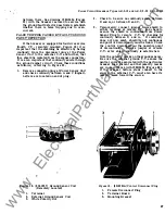
The typical overcurrent trip device consists
of a magnetic structure, a series current coil,
and a pivoted armature.
When current flow through the series coil
generates a magnetic field strong enough, the
armature overcomes the restraining force of a
calibration spring attached to it, and closes against
the magnet.
This trips the breaker by means
of an extension on the armature which strikes
against a trip paddle on the trip shaft.
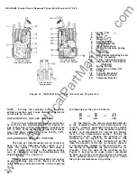
Depending on the type of individual device,
the movement of the armature may be delayed
for a time by a timing device.
If
a relatively
long time-delay (seconds or minutes) is desired,
the velocity of armature movement is governed
by a piston moving through an oil dashpot.
If
only a short-time delay (cycles or milli-seconds)
is required, movement is controlled by an escape
ment gear and pallets arrangement.
An AK-2- 1 5/2 5 breaker may be equipped with
either the EC-2 or EC- 1 overcurrent trip device.
The majority of applications will require the use
of the EC-2 device. The EC- 1 device is normally
2 0
used when the short-time delay feature i s required,
or when the trip device is used to operate a special
over-current alarm switch.
Most circuit breakers are equipped with series
overcurrent trip devices either of the dual magnetic
type (instantaneous and. time delay tripping) or
instantaneous alone.
Breakers are designed to
carry up to 100% of the continuous current rating
of their trip devices. Any attempt to carry higher
currents for a prolonged period will cause over
heating and possible damage .
E C-2 OVERCURRENT TRIP DEVICE
The Type EC-2 overcurrent tripping device
is available in three forms :
1. Dual overcurrent trip, with long-time delay
and high-set instantaneous tripping.
2 . Low-set instantaneous tripping .
3.
High- set instantaneous tripping.
The dual trip has adjustable long-time and
instantaneous pick-up settings and adjustable time
s ettings. Both forms of instantaneous trips have
adjustable pick-up settings .
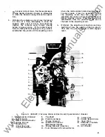
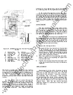
DUAL OVERCURRENT TRIP, WITH LONG- TIME
DELAY AND HIGH-SET INSTANTANEOUS TRIP
PING.
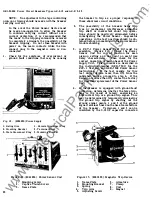
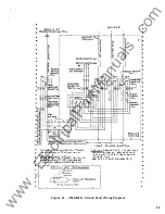
By means of the adjustment knob (5), Figure 10,
which can be manipulated by hand, the current
pick-up point can be varied from 80 to 160 percent
of the series coil rating.
The indicator and a
calibration plate
(4),
Figure 10, on the front of
the case provide a means of indicating the pick-up
point setting in terms of percentage of coil rating.
The calibration plate is indexed at percentage
settings of 80, 1 00, 120, 140 and 160.
•
www
. ElectricalPartManuals
. com


