GE AK-2A-15 User Maintenance Manual Download Page 21

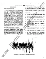
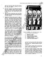
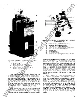
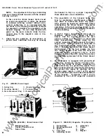
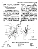
Figure  1 0.  (8024842)  EC-2 Overcurrent  Trip 

1 .   Series  Coil 

2. 

Trip  Adjustment Screw 

3.  Opening for  Time  Adjustment 

4. 

Pickup  Indicator 

Calib.  Plate 

5. 

Pickup  Adjustment Knol;> 

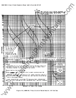
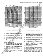
The  long-time  delay  tripping  feature  can  be 

supplied  with  any  one  of  three time-current char­

acteristics  which  correspond  to  the  NEMA  stand­

ards  maximum,  intermediate  and  minimum  long­

time  delay  operating  bands .  These  are  identified 

as  1A,  1B  and  1 C  characteristics,  respectively. 

Approximate  tripping  time  for  each  of  these,  in 

the  same  order  are  30, 

1 5  

and 

seconds  at  600% 

of the  pick-up value  of  current.  (See  time-current 

characteristic  curves  286B201A,  B,  and 

C). 

The  tripping  time  may  be  varied  within  the 

limits shown on the characteristic curves by turning 

the  time  adjustment  screw 

(5), 

Figure  1 1.  Turning 

in  a  clockwise direction increases the tripping time; 

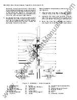
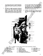
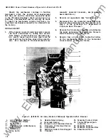
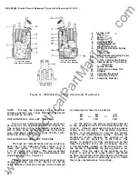
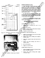
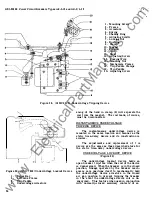
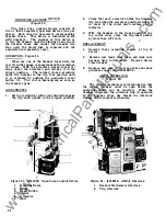
Figure  1 1.  (8024843) EC-2 Overcurrent Trip With 

Cover  Removed. 

1 .   Instantaneous  Calibration  Spring 

2.  Movable  Nut  (Index  Pointer) 

3.  Time-Delay  Calibration Spring 

4.  Instantaneous  Pickup  Adjustment Screw 

5. 

Time-Delay  Adjustment Screw 

6.  Oil Dashpot 

7.  Dashpot Arm 

8.  Connecting  Link 

9.  Instantaneous Pickup  Calibration  Marks 

counter-clockwise  motion decreases  it.  The dash­

pot  arm  (7),  Figure  1 1   is  indexed  at four points, 

maximum  - 2/3  - 1/3  - minimum  from  the  left, 

as  viewed  in  Figure  1 1.  When the  index  mark on 

the  connecting  link  (8),  Figure  1 1 ,  lines up  with a 

mark on the  dashpot arm,  the  approximate tripping 

time  as  shown  by  the  charaCteristic  curve  is  in­

dicated 

• 

The  1A  and 1B characteristic devices  are 

shipped  with  this  setting  at  the  2/3  mark and the 

lC  characteristic  at  the  1/3  mark.  The  standard 

characteristic  curves  are  plotted  at  the  same 

settings. 

Time  values  are  inversely  proportional  to 

the  effective  length  of  the  dashpot  arm.  There­

fore,  the  linkage  setting  that  gives  the  shortest 

time  value  is  the  one  at  which  dimension  "A" 

Figure  1 1,  is  greatest. 
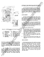
The  time  adjustment 

screw 

(5), 

Figure  1 1 ,   may  be  turned by  inserting 

a  Phillips  head  screwdriver  through  the  hole  in 

the  front  of  the  case,  but if  it  is  desired to  relate 

the  linkage  setting  to  the  index  marks  on  the 

linkage  it  will  be  necessary  to  remove  the  case. 

This  may  be  done  by  removing  the  two  mounting 

screws,  one  on  each  side  of  the  case,  which 

may  be  taken  off  without  disturbing  the  trip  unit 

itself. 

2 1  

www 

. ElectricalPartManuals 

. com 

Summary of Contents for AK-2A-15

Page 1: ...nance Instructions Includes Supplement GEI 86153 GEI 50299E Power Circuit Breakers Types AK 2 2A 15 AK 2 3 2A 3A 25 AKU 2 3 2A 3A 25 GENERAL fj ELECTRIC w w w E l e c t r i c a l P a r t M a n u a l s...

Page 2: ...Cut Off t Jwitch Closing Switch Shunt Trip Device PROTECTIVE DEVICES Overcurrent Trip Device EC 2 Overcurrent Trip Device EC 1 Overcurrent Trip Device Reverse Current Trip Devices Power lensor Trip D...

Page 3: ...forces the shorter end of the handle upwards against the bottom of the solenoid armature and closes the breaker The breaker may be tripped open by any one of a number of electrical tripping devices w...

Page 4: ...manual handle cam and mechanism connecting link The Tripping is accomplished by the manual trip button on the escutcheon or by any of the electrical tripping devices available for use on the standard...

Page 5: ...urrent carrying parts of the breaker and their supporting structure The procedure for this operation is as follows 1 Remove the arc quenchers see section on Arc Quenchers 2 Disconnect the two insulate...

Page 6: ...lease of tripping latch check mechanism latch adjustment Worn or damaged trip unit parts Replace trip unit Bind in overcurrent trip device Replace overcurrent trip device False Tripping Overcurrent tr...

Page 7: ...ts and external control circuits They are used only on drawout type breakers A terminal board serves the same purpose on stationary mountedandgeneral purpose enclosure mounted breakers The second ary...

Page 8: ...e rear side of the stationary contacts Each of the stationary contacts pivot in a horizontal plane approximately at their mid points The end of the contact opposite to the contact tip end is formed in...

Page 9: ...ontact replacement will call for re placement of all the movable and stationary con tacts at the same time This will be the case where long use of the breaker in service has resulted in extensive wear...

Page 10: ...r Base 8 Spring REPLACEMENT OF MOVAB LE C ONTACTS 18 Figure 3 1 Coat the pivot area only of the new movable contacts with a thin coat of D50H47 grease 2 Assemble the center pole movable contacts align...

Page 11: ...hould be adjustable using eccentric numbers 1 2 or 3 These numbers are the ones visible when viewing the breaker from the front not from above The higher numbers should be reserved for tightening at f...

Page 12: ...function properly it is best to first perform the available remedial measures listed in the Trouble Shooting chart of these instructions One of the remedies 12 listed is that of proper mechanism latch...

Page 13: ...position where the contacts move before tripping occurs When this position is established note the position of the slot in the head of the adjusting screw 4 Withdraw the adjusting screw three and one...

Page 14: ...e Arc Quencher 3 Disconnect the two insulated connecting links between the mechanism and the contacts as in step 2 of the procedure for Separation of Front and Back Frames 4 Remove the two elastic sto...

Page 15: ...bly In replacing the escutcheon it may be necessary to use pliers to pull the operating shaft fully into the escutcheon in order to have space enough to replace the flat washers and the soft retainer...

Page 16: ...g axis and withdraw it Replace new contacts by reversing the pro cedure slide downward until clear of armature Coil 6 Reassemble with new coil by reversing order of procedure X C ONTACTOR The X contac...

Page 17: ...s so that enough wire will remain for connection to the new relay Sufficient original wire is allowed for this purpose 2 JL_ lJ L c 3 4 5 After the old relay has been removed the wire leads to the rel...

Page 18: ...ide also holds a wiring cleat and spacer which serves to hold the wires clear of the link connecting the mechanism andthe breaker position indicator 4 Remove the front escutcheonfrom the breaker 5 Sli...

Page 19: ...Push Button 1 Nut 2 Frame 3 Spring 4 Rivet 5 Weight 5 Movable Contact 6 Spring 7 Hinge 8 Closing Solenoid _ L _ AUX SW LIC A7 M T C A M2 9 Speed Nut 10 Screw TRIP 3 1 1 Figure 9 695C161 Shunt Trip Dev...

Page 20: ...ice the movement of the armature may be delayed for a time by a timing device If a relatively long time delay seconds or minutes is desired the velocity of armature movement is governed by a piston mo...

Page 21: ...shpot Arm 8 Connecting Link 9 Instantaneous Pickup Calibration Marks counter clockwise motion decreases it The dash pot arm 7 Figure 1 1 is indexed at four points maximum 2 3 1 3 minimum from the left...

Page 22: ...instantaneous pick up value may have one of the following three ranges 4 to 9 times coil rating 6 to 12 times coil rating or 9 to 15 times coil rating The pick up setting may be varied by turning the...

Page 23: ...overcurrent trip devices have been replaced Positive tripping is achieved when adjustment screw 2 Figure 10 is in such a position that it will always carry the trip paddle on the trip shaft beyond the...

Page 24: ...against trip paddle 14 tripping thebreaker open ADJUSTMENTS The only adjustment to be made on the reverse current device is to make sure that the trip rod has a minimum overtravel of 1 32 of an inch...

Page 25: ...nciple that the instantaneous value of current flowing in the three conductors or in four conductors on four wire systems must add to zero unless ground current is flowing Therefore if the electrical...

Page 26: ...Power Sensor Successful operations in the test position should be ob tained before proceedingwith the Power Sensor trouble shooting 3 A PST 1 Power Sensor Test Kit must be available Figure 21 Check t...

Page 27: ...Coil Remotely Located 1 Terminal 2 External Ground Sensor Coil 3 White Polarity Dot 2 Check to be sure no continuity exists between R and A or between R and C 3 Temporarily connect jumper from shield...

Page 28: ...ngle phase testing unless the signal is shorted at the terminal board Figure 22 Jumper points 1 and 5 during overcurrent test The above considerations shouldindicate which of the four major components...

Page 29: ...C CONTtt ii IT R TO IEt O 1 tE tJi AL c 5RDUNO SEN SO COi l n n 75 11 Jt 50U R C E T P I C L f 0 JtJD F A JLT Co i E TiON eREAK E i 1 C t l 1 G eOuiJD SENSO OiSCO t4 IE i A NC ttlC T R NAl Gi OUNO 5SN...

Page 30: ...NGE AVA IL ABLE PER D E V ICE R A N G E OF 6 TO 12 T IMES IS F U RNISHED U N L E S S 1 f fi H I I I I I I O T H E RW I S E SPECIFI E D S E T T I NGIS ARE AT 12 T IM E S RATING r TOTA L cURVES ARE P L...

Page 31: ...TIIP liniNG Figure 25 109HL689 Time Curve 5 Unsolder three leads at ground disconnect and pull wire through hole in back frame On stationary breakers withfourthwire ground disconnect unsolder leads at...

Page 32: ...o wiring diagram 0102C3698 Figure 26 The voltage 208V AC or 230V AC to be monitored is connected to terminals 1 and 2 of the time delay box The undervoltage device 32 R T t C o N NE c T tr o c T O ME...

Page 33: ...unit is the faulty component A B Check input voltages across terminals 1 2 on static box These voltages should be as follows 1 Device 177L3 16 G 12 208 or 230volts A C 2 Device 177L316 G 14 125 volts...

Page 34: ...y device and its construction is similar The adjustments and replacement of t is device are the same as those described above for the static time delay undervoltage device UNDERVOLTAGE LOCKOUT DEVICE...

Page 35: ...eaker opens lever 2 rotates counterclockwise about pin 14 The motion is transmitted through links 1 and 13 to paddle 12 which operates bell alarm switch 11 If the device has the lockout feature the mo...

Page 36: ...wn to engage the trip shaft paddle in the tripped position 1 Figure 31 8041865 Open Fuse Lockout Device 1 Mounting Holes 2 Lever 3 Reset Button 4 Collor 5 Armature 6 Coil 36 4 2 Check that each armatu...

Page 37: ...embly of the existing backframe with the new front frame Addition of Shunt Trip Device Auxiliary witch Undervoltage Device Bell Alarm Lockout Device Drawout Mechanism Conversion to Elec Oper Covered B...

Page 38: ...w w w E l e c t r i c a l P a r t M a n u a l s c o m...

Page 39: ...w w w E l e c t r i c a l P a r t M a n u a l s c o m...

Page 40: ...further information call or write your local General Electric Sales Office or Distribution Equipment Division 41 Woodford Avenue Plainville CT 06062 USA GENERAL fl ELECTRIC w w w E l e c t r i c a l P...

Reviews: