background image

1 Introduction 

P50 Agile P153  


1-8 

P153/EN M/B 


Summary of Contents for Agile P50 Series

Page 1: ...GE Grid Solutions P50 Agile P153 Technical Manual Compact Feeder Protection Relay Hardware version A Software version 01 Publication reference P153 EN M B...

Page 2: ...2014 30 EU and product safety Low voltage directive 2014 35 EU This conformity is the result of a test conducted in accordance with the product standard EN 60255 26 for the EMC directive and with the...

Page 3: ...P50 Agile P153 1 Introduction P153 EN M B 1 1 INTRODUCTION CHAPTER 1...

Page 4: ...1 Introduction P50 Agile P153 1 2 P153 EN M B...

Page 5: ...This chapter consists of the following sections 1 Chapter Overview 2 Introduction 2 1 Features 2 1 1 Protection Control 2 1 2 Measurement Recording Post Fault Analysis 2 1 3 Front Panel Interface 2 1...

Page 6: ...t supervision functions Multiple setting groups are included The hardware capability is broadened by offering minimum ordering options to permit standardisation in procurement and inventories The user...

Page 7: ...5 disturbance records 2 1 3 Front Panel Interface 6 LEDs for status indication Backlit LCD display 16 x 2 6 navigation keys for setting and interrogation 2 1 4 Communications Front USB port for real...

Page 8: ...atus LEDs Communication USB port Modbus IEC 60870 5 103 Binary Input Output Binary Input 4 ungrouped Binary Output 4 2NO 2C O Analogue Input Phase current input 3x1 ph Earth current input 1x1 ph Gener...

Page 9: ...V DC 75V AC 3 Current Transformer Phase Neutral CT 1A 5A 1 Hardware Options USB front port and RS485 rear port 1 I O Options Standard 4 logic inputs 4 relay outputs A Communication Protocol Modbus IEC...

Page 10: ...1 Introduction P50 Agile P153 1 8 P153 EN M B...

Page 11: ...P50 Agile P153 2 Safety Information P153 EN M A 2 1 SAFETY INFORMATION CHAPTER 2...

Page 12: ...ith the installation commissioning and operation of the equipment and the system to which it is being connected familiar with accepted safety engineering practises and are authorised to energise and d...

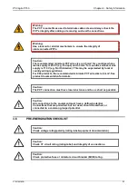
Page 13: ...e to do so could result in damage to the equipment Warning Risk of electric shock Warning Risk of damage to eyesight Earth terminal Note This symbol may also be used for a protective conductor earth t...

Page 14: ...personnel involved in installing commissioning or servicing this equipment must be familiar with the correct working procedures Caution Consult the equipment documentation before installing commissio...

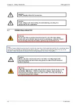
Page 15: ...to zero before disconnecting test leads Caution Operate the equipment within the specified electrical and environmental limits Caution Before cleaning the equipment ensure that no connections are ene...

Page 16: ...s to 0 5 Nm minimum and 0 6 Nm maximum Caution Always use insulated crimp terminations for voltage and current connections Caution Always use the correct crimp terminal and tool according to the wire...

Page 17: ...a This may be superseded by local or country wiring regulations For P60 products the recommended minimum PCT wire size is 6 mm See product documentation for details Caution The PCT connection must hav...

Page 18: ...ith ring terminal connections the threaded terminal block for current transformer termination is automatically shorted if the module is removed Therefore external shorting of the CTs may not be requir...

Page 19: ...connected equipment shall be connected directly to the same equipotential bonded earthing system iv If for any reason both ends of the cable screen are not connected to the same equipotential bonded e...

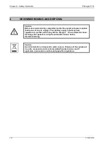
Page 20: ...ply The auxiliary supply input may have capacitors in parallel which may still be charged To avoid electric shock discharge the capacitors using the external terminals before decommissioning Caution A...

Page 21: ...monized standard s or conformity assessment used to demonstrate compliance with the LVD directive Safety related information such as the installation I overvoltage category pollution degree and operat...

Page 22: ...Chapter 2 Safety Information P50 Agile P153 2 12 P153 EN M A...

Page 23: ...P50 Agile P153 3 Hardware Design P153 EN M B 3 1 HARDWARE DESIGN CHAPTER 3...

Page 24: ...3 Hardware Design P50 Agile P153 3 2 P153 EN M B...

Page 25: ...Chapter Overview 2 Hardware Design 2 1 Overview of Hardware design 2 2 Microcontroller with DSP module 2 2 1 Microcontroller module Processor board features 2 3 Microcontroller and analog measurement...

Page 26: ...hardware comprises of following main components Housing consisting of a front panel and connections at the rear Microcontroller module Analogue input module Digital input module Digital output module...

Page 27: ...ts power supply input of 24 50V DC or 110 230 V AC DC from external source and outputs 12 V and 24 V DC for internal circuitry The current signals acquired as analogue inputs get processed through ope...

Page 28: ...dules like 16x2 LCD display feather touch keys USB and RS485 communication interfaces battery backup for RTC and built in memory circuits are integrated as per the schematic diagram and enclosed in th...

Page 29: ...The relay hardware uses external 16 bit ADC converter with capability to sample 8 signals simultaneously to avoid any phase angle error and achieve higher accuracy In P153 only 4 channels of ADC conv...

Page 30: ...Earth Fault and Negative phase sequences The actual protection function depends on type of relay and described in the rest of the document 2 4 Digital input output module This module supports 4 number...

Page 31: ...man machine interface module The HMI module is provided with 16x2 LCD 6 numbers of soft feather touch keys and 6 numbers of LEDs for indication The front panel houses following Female USB connector Mo...

Page 32: ...3 Hardware Design P50 Agile P153 3 10 P153 EN M B...

Page 33: ...P50 Agile P153 4 Front Panel P153 EN M B 4 1 FRONT PANEL CHAPTER 4...

Page 34: ...4 Front Panel P50 Agile P153 4 2 P153 EN M B...

Page 35: ...t Panel P153 EN M B 4 3 1 CHAPTER OVERVIEW This chapter consists of the following sections 1 Chapter Overview 2 Front Panel 2 1 User Interface 2 1 1 LCD Display 2 1 2 Touch Keys 2 1 3 LEDs 2 1 4 RS 48...

Page 36: ...ED switches OFF after pressing CLEAR key 4 OUT OF SERVICE Amber LED flashes when the IED s protection is unavailable eg Setting error ADC error detected by unit s self test etc 5 L5 Programmable dual...

Page 37: ...d INCREASE the values key is used for navigating through the menus submenus and to save the settings key is used to view the settings and to navigate through the menus and submenus key is used to chan...

Page 38: ...of relay near to terminal block for permanent SCADA connectivity The separate 3 pin connector is used to avoid accidental connection of power wiring to communication input The RS485 port can be used...

Page 39: ...P50 Agile P153 5 Configuration P153 EN M B 5 1 CONFIGURATION CHAPTER 5...

Page 40: ...P50 Agile P153 5 Configuration P153 EN M B 5 2...

Page 41: ...Configuration Menu 2 3 8 1 View Edit Settings 2 3 9 Transformer Ratios Menu 2 3 9 1 View Edit Settings 2 3 10 Record Control Menu 2 3 10 1 View Edit Settings 2 3 11 Communication Menu 2 3 11 1 View E...

Page 42: ...gs 2 4 15 O P Relay Configuration Menu 2 4 15 1 View Edit Settings 2 4 16 Disturbance Record Menu 2 4 16 1 View Edit Settings 2 4 17 Commissioning Test Menu 2 4 17 1 View Edit Settings 2 4 18 Group1 M...

Page 43: ...Settings If Characteristics is set as Single 2 4 24 Group 1 Cold Load Pickup Submenu 2 4 24 1 View Edit Settings 2 4 24 2 View Edit Settings I 1 Function 2 4 25 Group 1 Undercurrent Submenu 2 4 25 1 V...

Page 44: ...rs This chapter describes an overview of this common methodology as well as providing concise instructions of how to configure the device Using the HMI you can Display and modify settings View the dig...

Page 45: ...e Password press the EDIT key the Password OK message is displayed and settable number text will start blinking and the relay will move to the next option Note When the password is set modification ca...

Page 46: ...ssword 3 Press the 3 key to confirm the password After entering a valid password the Password OK message appears indicating that the password is correct The user can now start editing the settings If...

Page 47: ...pen Pulse Time DATE AND TIME Password protected window for DATE AND TIME settings i e Local Time Enable Local Time Offset DST Enable DST Offset DST Start DST Start Day DST Start Month DST Start Mins D...

Page 48: ...s GROUP 1 Password protected window for GROUP 1 settings i e SYSTEM CONFIG OVERCURRENT NEG SEQUENCE O C BROKEN CONDUCTOR EARTH FAULT 1 EARTH FAULT 2 THERMAL OVERLOAD COLD LOAD PICKUP UNDERCURRENT and...

Page 49: ...Hz Editable setting This window shows the System Frequency The desired Frequency can be selected to either 50 60 Hz USB Address 1 Read only This window shows the USB Address USB Parity None Read only...

Page 50: ...tion Opto I P DC Editable setting This window allows selection of voltage input type for the Opto I P i e AC DC Config Port USB Editable setting This window allows selection of the Configuration Port...

Page 51: ...tection function I 2 IN1 2 IN2 2 I2 2 This window will show trip flag of stage 2 O C E F 1 and E F 2 Neg Sequence O C Note This window is seen when relay operates for respective protection function I...

Page 52: ...w will show secondary fault current values Thermal State 0 This window will show Thermal State Trip Counter 0 This window will show Trip counter Trip Timing Sec 0 000 This window will show Trip time 1...

Page 53: ...225 This window will show date time of Event Event Num 1 Trip IN1 This window shows the latest Event and Event number 2 3 4 4 View Maintenance Records VIEW RECORDS This menu is to view Fault Record E...

Page 54: ...larm Records VIEW RECORDS This menu is to view Fault Record Event Record Maint Record and Alarm record Fault Record This window shows the Fault Record Event Record This window will show Event Record M...

Page 55: ...This window shows primary value of current in phase C and measured earth current taking in account phase CT and earth CT ratio respectively IN2 0 A This window shows primary value of internally derive...

Page 56: ...P50 Agile P153 5 Configuration P153 EN M B 5 18 BOT 0 msec Th State 0 This window shows Breaker operating time and actual Thermal State...

Page 57: ...l By Close Pulse Time and Open Pulse Time TCS Alarm NO Editable setting By using the 5 or 6 key TCS Alarm can be set as Yes No CB Open S vision Disabled Editable setting By using the 5 or 6 key CB Ope...

Page 58: ...set The setting range is from 0 1s to 10 00s in steps of 10ms CB Open S vision Enabled Editable setting By using the 5 or 6 key CB Open Supervision can be Enabled or Disabled CB Open Time 0 30S Edita...

Page 59: ...Offset DST Enable DST Offset DST Start DST Start Day DST Start Month DST Start minutes DST End DST End Day DST End Month DST End minutes RP Time Zone SET Hours SET Minutes SET Seconds SET Date SET Mo...

Page 60: ...6 key SET Year can be set The setting range is from 0 to 99 in steps of 1 2 3 7 2 Edit Settings if the settings are enabled DATE AND TIME Password protected window for DATE AND TIME settings Local Tim...

Page 61: ...DST Start Day can be set from Sunday to Saturday DST Start Month March Editable setting By using the 5 or 6 key DST Start Month can be set from January to December DST Start Mins 60 Mins Editable Set...

Page 62: ...SET Minutes 21 Editable setting By using the 5 or 6 key SET Minutes can be set The setting range is from 0 to 59 in steps of 1 SET Seconds 50 Editable setting By using the 5 or 6 key SET Seconds can b...

Page 63: ...etting Values Restore Defaults No Operation Editable setting By using the 5 or 6 key Restore Defaults can be set as No Operation All Settings Setting Group 1 Setting Group 2 Active Settings Group 1 Ed...

Page 64: ...ng By using the 5 or 6 key Earth Fault 1 can be Enabled or Disabled Earth Fault 2 Enabled Editable setting By using the 5 or 6 key Earth Fault 2 can be Enabled or Disabled Thermal Overload Disabled Ed...

Page 65: ...itable setting By using the 5 or 6 key Phase CT Primary can be set The setting range is from 1A to 30000A step 1A Phase CT Sec y 1 A Editable setting By using the 5 or 6 key Phase CT Secondary can be...

Page 66: ...Maintenance Record data stored in memory Thermal Reset No Editable setting By using the 5 or 6 key Thermal Reset can be set as Yes No set Yes to reset Thermal State to zero 2 3 11 Communication Menu 2...

Page 67: ...g By using the 5 or 6 key LED RED can be set for desired function 5 corresponds to LED L5 6 corresponds to LED L6 Set the value 1 for assigned 0 for not assigned under the numbers representing LED RED...

Page 68: ...P RELAY CONFIGURATION settings Contact HR SR O P 1 Open Time O P 2 Open Time O P 3 Open Time and O P 4 Open Time LED G HR SR LED R HR SR ANDEQ A Op Time ANDEQ Rst Time ANDEQ B Op Time ANDEQ B Rst Time...

Page 69: ...Time can be set The setting range is from 1 to 3600s in steps of 1s ANDEQ B Rst Time 1 S Editable setting By using the 5 or 6 key the desired AND Equation B Reset Time can be set The setting range is...

Page 70: ...Test settings Test Mode Test Pattern Contact Test and Test LEDs Test Mode Disabled Editable setting By using the 5 or 6 key Test Mode be set as Disabled Test Mode Contacts Blocked Test Pattern 0000 E...

Page 71: ...Password protected window for Negative Sequence O C i e I2 1 Function I2 2 Function and I2 3 Function The functions can be set as Disabled DT IDMT Note Setting will be seen only when it is enabled in...

Page 72: ...ndow for GROUP 1 settings SYSTEM CONFIG OVERCURRENT NEG SEQUENCE O C BROKEN CONDUCTOR EARTH FAULT 1 EARTH FAULT 2 THERMAL OVERLOAD COLD LOAD PICKUP UNDERCURRENT and CB FAIL Note Group 1 Setting will b...

Page 73: ...setting to Disabled DT IEC S Inverse S Inverse 1 3Sec IEC V Inverse IEC E Inverse UK LT Inverse IEEE M Inverse IEEE V Inverse IEEE E Inverse US Inverse US ST Inverse I 1Function Disabled Editable sett...

Page 74: ...01s I 1 2H Blocking Disabled Editable setting By using the 5 or 6 key I 12H Blocking function can be Enabled Disabled 2 3 16 3 3 Edit Settings if I 1 Function is selected for IEEE US curve GROUP 1 Pa...

Page 75: ...setting By using the 5 or 6 key I 12H Blocking function can be Enabled Disabled 2 3 16 3 4 Edit Settings if I 1 Function is selected for DT GROUP 1 Password protected window for GROUP 1 setting SYSTEM...

Page 76: ...f I2 1 Function I2 2 Function and I2 3 Function are disabled GROUP 1 Password protected window for GROUP 1 setting SYSTEM CONFIG OVERCURRENT NEG SEQUENCE O C BROKEN CONDUCTOR EARTH FAULT 1 EARTH FAULT...

Page 77: ...Inverse 1 3Sec IEC V Inverse IEC E Inverse UK LT Inverse IEEE M Inverse IEEE V Inverse IEEE E Inverse US Inverse US ST Inverse I2 1 Function IEC S Inverse Editable setting By using the 5 or 6 key I2...

Page 78: ...able setting By using the 5 or 6 key I2 1 Function is set as IEEE M Inverse I2 1 Current Set 1 00 A Editable setting By using the 5 or 6 key I2 1 Current Setting can be set The setting range is from 0...

Page 79: ...DT Editable setting By using the 5 or 6 key I2 1Function is set as DT Definite Time I2 1 Current Set 1 00 A Editable setting By using the 5 or 6 key I2 1 Current Setting can be set The setting range i...

Page 80: ...ng the 5 or 6 key BC Alarm is Disabled BC Trip Disabled Editable setting By using the 5 or 6 key BC Trip is Disabled 2 3 16 5 2 Edit Settings if function is enabled GROUP 1 Password protected window f...

Page 81: ...nction and IN1 3 Function are disabled GROUP 1 Password protected window for GROUP 1 settings SYSTEM CONFIG OVERCURRENT NEG SEQUENCE O C BROKEN CONDUCTOR EARTH FAULT 1 EARTH FAULT 2 THERMAL OVERLOAD C...

Page 82: ...t as Disabled DT IEC S Inverse S Inverse 1 3Sec IEC V Inverse IEC E Inverse UK LT Inverse IEEE M Inverse IEEE V Inverse IEEE E Inverse US Inverse US ST Inverse Measured Read only Description for Earth...

Page 83: ...ec IEC V Inverse IEC E Inverse UK LT Inverse IEEE M Inverse IEEE V Inverse IEEE E Inverse US Inverse US ST Inverse Measured Read only Description for Earth Fault 1 IN1 1 Function IEEE M Inverse Editab...

Page 84: ...and IN1 3 Function which can be set as Disabled DT IEC S Inverse S Inverse 1 3Sec IEC V Inverse IEC E Inverse UK LT Inverse IEEE M Inverse IEEE V Inverse IEEE E Inverse US Inverse US ST Inverse Measu...

Page 85: ...L OVERLOAD COLD LOAD PICKUP UNDERCURRENT and CB FAIL Note Group 1 Setting will be seen only when it is enabled in Configuration setting EARTH FAULT 2 Password protected window for Earth Fault 2 derive...

Page 86: ...e IEEE V Inverse IEEE E Inverse US Inverse US ST Inverse Derived Read only Description for Earth Fault 2 IN2 1 Function IEC S Inverse Editable setting By using the 5 or 6 key IN2 1Function is set as I...

Page 87: ...erived Read only Description for Earth Fault 2 IN2 1 Function IEEE M Inverse Editable setting By using the 5 or 6 key IN2 1 Function is set as IEEE M Inverse IN2 1 Current Set 1 00 A Editable setting...

Page 88: ...EC S Inverse S Inverse 1 3Sec IEC V Inverse IEC E Inverse UK LT Inverse IEEE M Inverse IEEE V Inverse IEEE E Inverse US Inverse Derived Read only Description for Earth Fault 2 IN2 1 Function DT Editab...

Page 89: ...ad i e Characteristic Disabled Single Thermal Trip Thermal Alarm Time Constant 1 and K Characteristic Disabled Editable setting By using the 5 or 6 key Characteristic is set as Disabled 2 3 16 8 2 Edi...

Page 90: ...FAULT 2 THERMAL OVERLOAD COLD LOAD PICKUP UNDERCURRENT and CB FAIL Note Group 1 Setting will be seen only when it is enabled in Configuration setting COLD LOAD PKP Password protected window for Cold L...

Page 91: ...ble setting By using the 5 or 6 key IN2 2 Status can be Enabled Blocked IN1 3 Status Enabled Editable setting By using the 5 or 6 key IN2 3 Status can be Enabled Blocked IN2 1 Status Enabled Editable...

Page 92: ...atus IN1 1 Status IN1 2 Status IN1 3 Status IN2 1 Status IN2 2 Status and IN2 3 Status tcold Time Delay 7200 S Editable setting By using the 5 or 6 key tcold Time Delay can be set The setting range is...

Page 93: ...itable setting By using the 5 or 6 key tclp Time Delay can be set The setting range is from 0 to 14400 in steps of 1 I 1 Status Enabled Editable setting By using the 5 or 6 key I 1 Status is Enabled I...

Page 94: ...g By using the 5 or 6 key I 1 Current Set can be set The setting range is from 0 05 to 4 00 In in steps of 0 01 In I 1 Time Delay 0 01 S Editable setting By using the 5 or 6 key I 1 Time Delay can be...

Page 95: ...etting By using the 5 or 6 key I settings can be set The setting range is from 0 1 to 1 In in steps of 0 01 In t I 1 00 S Editable setting By using the 5 or 6 key t I setting can be set The setting ra...

Page 96: ...assword protected window for GROUP 1 setting i e SYSTEM CONFIG OVERCURRENT NEG SEQUENCE O C BROKEN CONDUCTOR EARTH FAULT 1 EARTH FAULT 2 THERMAL OVERLOAD COLD LOAD PICKUP UNDERCURRENT and CB FAIL Note...

Page 97: ...ROKEN CONDUCTOR EARTH FAULT 1 EARTH FAULT 2 THERMAL OVERLOAD COLD LOAD PICKUP UNDERCURRENT and CB FAIL Note Group 2 Setting will be seen only when it is enabled in Configuration setting SYSTEM CONFIG...

Page 98: ...Alarm Time Constant 1 and K COLD LOAD PICKUP Password protected window for Cold Load Pickup i e tcold Time Delay tclp Time Delay I 1 Status I 2 Status I 3 Status IN1 1 Status IN1 2 Status IN1 3 Status...

Page 99: ...isplayed and the user can scroll through the main menu as below ID 1 SW V1 00 SYSTEM DATA VIEW RECORDS MEASUREMENTS CB CONTROL DATE AND TIME CONFIGURATION TRANS RATIOS RECORD CONTROL COMMUNICATION IO...

Page 100: ...cy To change the System Frequency press the EDIT Key As soon as the Edit Key is pressed the relay will ask for Password By using the Up arrow key 5 or the Down arrow key 6 enter the set Password i e f...

Page 101: ...quency 50Hz USB Address 1 USB Parity None USB Baud Rate 57600 Password Active Group Group 1 Opto I P 4321 Status 0000 Relay O P 4321 Status 0000 3 For Save CLEAR For Cancel CB Open Close No Operation...

Page 102: ...P50 Agile P153 5 Configuration P153 EN M B 5 64 2 4 4 View Records Menu 2 4 4 1 View Content VIEW RECORDS Fault Record Event Record Maint Record 3 4 3 4 3 4 3 6 Alarm Record 3 4...

Page 103: ...In2 0 00 A I2 0 00 A Trip Counter 269 Trip Timing Sec 1 005 17 02 18 16 15 30 225 4 3 3 4 3 4 3 4 3 4 3 4 3 4 3 4 3 4 3 4 I 2 IN1 2 IN2 2 I2 2 I1 0 00 A I2 I1 0 00 Fault Record 3 4 4 4 3 4 3 4 3 4 3...

Page 104: ...Record 3 4 Event Num 1 Dt 21 02 2014 Tm 16 15 30 225 4 Event No 1 Power on 3 4 3 4 3 4 3 6 Event Num 2 3 4 2 4 4 4 View Maintenance Records Fault Record Event Record Maint Record 3 4 Main t Rec Num 4...

Page 105: ...P50 Agile P153 5 Configuration P153 EN M B 5 67 2 4 4 5 View Alarm Records Fault Record Event Record Maint Record TCS Alarm 24 09 2014 11 24 00 842 3 4 3 4 3 4 3 4 VIEW RECORDS 4 3 6 Alarm Record 3 4...

Page 106: ...Measurement Menu 2 4 5 1 View Measurements IA 0 A IB 0 A IC 0 A IN1 0 A IN2 0 A ia 0 00 A ib 0 00 A ic 0 00 A in1 0 00 A In2 0 00 A i1 0 00 A i2 0 00 A I2 I1 0 000 TC 269 BOC 257 BOT 0 mSec Th State 0...

Page 107: ...ettings are disabled TCS Alarm NO CB Open S vision Disabled CB Open Alarm Disabled CB Control by Disabled 3 4 3 4 3 4 6 CB CONTROL 34 3 4 3 For Save CLEAR For Cancel 34 SAVE Settings 3 CLEAR DISCARD S...

Page 108: ...led CB Open Time 0 30S CB Open Alarm Enabled CB Open Oper 2000 CB Control by Local Remote Close Pulse Time 0 50S Open Pulse Time 0 50S 3 4 3 4 3 4 3 4 3 4 3 4 3 4 3 4 6 CB CONTROL 3 4 34 3 For Save CL...

Page 109: ...Wed Local Time Enable Disabled DST Enable Disabled RP Time Zone Local 4 3 4 3 4 3 4 SET Hours 17 3 4 3 4 SET Minutes 21 3 4 SET Seconds 50 3 4 SET Date 17 3 4 SET Month 2 3 4 SET Year 18 3 4 34 3 4 3...

Page 110: ...ST Start Month March DST Start Mins 60 Mins DST End Last DST End Day Sunday DST End Month October DST End Mins 30 Mins RP Time Zone Local 4 3 4 3 4 3 4 3 4 3 4 3 4 3 4 3 4 3 4 3 4 3 4 SET Hours 17 3 4...

Page 111: ...t Enabled Neg Sequence O C Disabled Broken Conductor Disabled Earth Fault 1 Enabled Earth Fault 2 Enabled Thermal Overload Disabled Cold Load Pickup Disabled 3 4 3 4 3 4 3 4 3 4 3 4 3 4 3 4 3 4 Measur...

Page 112: ...Settings TRANS RATIOS Phase CT Primary 100 A Phase CT Sec y 1 A E F CT Primary 100 A E F CT Secondary 1 A 3 4 3 4 3 4 3 4 34 6 3 For Save CLEAR For Cancel 34 SAVE Settings 3 CLEAR DISCARD Settings ED...

Page 113: ...ttings RECORD CONTROL Clear Events No Clear Faults No Clear Dist Recs No Clear Maint No 3 4 3 4 3 4 3 4 Thermal Reset No 3 4 34 6 3For Save CLEAR For Cancel 34 SAVE Settings 3 CLEAR DISCARD Settings E...

Page 114: ...dit settings COMMUNICATION RP1 Address 1 RP1 Baud Rate 57600 RP1 Parity Even 3 4 3 4 3 4 RP1 Timesync Disabled 3 4 34 6 3 For Save CLEAR For Cancel 34 SAVE Settings 3 CLEAR DISCARD Settings EDIT Note...

Page 115: ...n Strt 00 LED R 65 Gen Strt 00 AND Logic DCBA Gen Strt 0000 Opto I P 4321 Rem Rst 0000 6 5 Relay 4321 Gen Strt 0000 6 5 6 5 6 5 4 6 IO CONFIGURATION 3 For Save CLEAR For Cancel 4 SAVE Settings 3 CLEAR...

Page 116: ...21 Strt I 2 0000 Relay 4321 Strt I 3 0000 Relay 4321 Strt I2 1 0000 3 4 3 4 3 4 Relay 4321 Strt I2 2 0000 Relay 4321 Strt I2 3 0000 Relay 4321 Strt IN1 1 0000 Relay 4321 Strt IN1 2 0000 3 4 3 4 3 4 3...

Page 117: ...elay 4321 Trip I 1 0000 Relay 4321 Trip I 2 0000 Relay 4321 Trip I 3 0000 Relay 4321 Trip I2 1 0000 3 4 3 4 3 4 3 4 Relay 4321 Trip I2 2 0000 Relay 4321 Trip I2 3 0000 Relay 4321 Trip IN1 1 0000 3 4 3...

Page 118: ...000 Relay 4321 Trip I 0000 3 4 3 4 3 4 3 4 Relay 4321 OptoI P 3 0000 Relay 4321 OptoI P 4 0000 3 4 3 4 Relay 4321 AndLogicA 0000 Relay 4321 AndLogicB 0000 Relay 4321 AndLogicC 0000 Relay 4321 AndLogic...

Page 119: ...I P 4321 Blk I 2 0000 Opto I P 4321 Blk I 3 0000 Opto I P 4321 Blk I2 1 0000 Opto I P 4321 Blk I2 2 0000 3 4 3 4 3 4 3 4 Opto I P 4321 Blk I2 3 0000 Opto I P 4321 Blk IN1 1 0000 Opto I P 4321 Blk IN1...

Page 120: ...Time 1 S 3 4 3 4 3 4 3 4 3 4 3 4 3 4 O P RELAY CONFIG O P 1 Open Time 0 50 S LED G HR SR 00 LED R HR SR 00 3 4 3 4 ANDEQ C Rst Time 1 S ANDEQ D Op Time 1 S ANDEQ D Rst Time 1 S 3 4 3 4 3 4 ANDEQ C Op...

Page 121: ...isturbance Record Menu 2 4 16 1 View Edit Settings DISTURBANCE REC Trigger Position 50 3 4 3For Save CLEAR For Cancel 34 SAVE Settings 3 CLEAR DISCARD Settings EDIT Note indicates Edit key used to mod...

Page 122: ...Settings COMMISSION TEST Test Mode Disabled Test Pattern 0000 Contact Test No Operation 3 4 3 4 3 4 Test LEDs No Operation 3 4 34 6 3For Save CLEAR For Cancel 34 SAVE Settings 3 CLEAR DISCARD Settings...

Page 123: ...EM CONFIG OVERCURRENT NEG SEQUENCE O C BROKEN CONDUCTOR EARTH FAULT 1 EARTH FAULT 2 THERMAL OVERLOAD COLD LOAD PICKUP UNDER CURRENT 3 4 3 4 3 4 3 4 3 4 3 4 3 4 3 4 3 4 CB FAIL 3 4 Note Only those Prot...

Page 124: ...3 For Save CLEAR For Cancel 4 SAVE Settings 3 CLEAR DISCARD Settings EDIT 4 2 4 18 2 2 View Edit Settings If the setting is enabled 2nd Harmonic Enabled 2nd Harm Thresh 20 I lift 2H 10 00 A 3 4 3 4 4...

Page 125: ...tings If the setting is disabled OVER CURRENT I 1 Function Disabled 4 GROUP 1 I 2 Function Disabled I 3 Function Disabled 3 4 3 4 3 4 3 4 3 4 3 For Save CLEAR For Cancel 4 SAVE Settings 3 CLEAR DISCAR...

Page 126: ...0 A I 1 TMS 1 000 3 4 3 4 I 1 Reset Char DT 3 4 I 1 tRESET 1 00 S 3 4 I 1 2H Blocking Disabled 3 4 OVER CURRENT I 1 Function IEC S Inverse GROUP 1 3 4 3 4 4 6 3 For Save CLEAR For Cancel 4 SAVE Settin...

Page 127: ...et Char DT 3 4 I 1 tRESET 1 00 S 3 4 I 1 2H Blocking Disabled 3 4 I 1 Reset Char IDMT 3 4 I 1 RTMS 1 000 3 4 I 1 2H Blocking Disabled 3 4 3 4 6 3 4 3 4 3 For Save CLEAR For Cancel 4 SAVE Settings 3 CL...

Page 128: ...ime Delay 1 00 S 3 4 3 4 I 1 Reset Char DT 3 4 I 1 tRESET 1 00 S 3 4 I 1 2H Blocking Disabled 3 4 I 1 Function DT OVER CURRENT 4 GROUP 1 6 3 4 3 4 3 For Save CLEAR For Cancel 4 SAVE Settings 3 CLEAR D...

Page 129: ...ttings If setting is disabled I2 1 Function Disabled NEG SEQUENCE O C 4 GROUP 1 3 4 3 4 3 4 3 4 3 4 I2 2 Function Disabled I2 3 Function Disabled 3 For Save CLEAR For Cancel 4 SAVE Settings 3 CLEAR DI...

Page 130: ...0 A I2 1 TMS 1 000 3 4 3 4 I2 1 Reset Char DT 3 4 I2 1 tRESET 1 00 S 3 4 I2 1 2H Blocking Disabled 3 4 I2 1 Function IEC S Inverse NEG SEQUENCE O C 4 GROUP 1 6 3 4 3 4 3For Save CLEAR For Cancel 4 SAV...

Page 131: ...ng Disabled 3 4 I2 1 Reset Char IDMT 3 4 I2 1 RTMS 1 000 3 4 I2 1 2H Blocking Disabled 3 4 3 4 I2 1 Function IEEE M Inverse NEG SEQUENCE O C 4 GROUP 1 6 3 4 3 4 3 For Save CLEAR For Cancel 4 SAVE Sett...

Page 132: ...A I2 1 Time Delay 1 00 S 3 4 3 4 I2 1 Reset Char DT 3 4 I2 1 tRESET 1 00 S 3 4 I2 1 2H Blocking Disabled 3 4 I2 1 Function DT NEG SEQUENCE O C 4 GROUP 1 6 3 4 3 4 3For Save CLEAR For Cancel 4 SAVE Set...

Page 133: ...1 View Edit Settings If setting is disabled BC Alarm Disabled BROKEN CONDUCTOR GROUP 1 3 4 3 4 BC Trip Disabled 3 4 4 3 For Save CLEAR For Cancel 4 SAVE Settings 3 CLEAR DISCARD Settings EDIT Note ind...

Page 134: ...I2 I1 Time Dly 1 10 00S 3 4 4 6 BC Alarm Enabled BROKEN CONDUCTOR GROUP 1 3 4 BC Trip Enabled 3 4 4 I2 I1Set 2 0 50 I2 I1 Time Dly 2 10 00S 3 4 4 3 For Save CLEAR For Cancel 4 SAVE Settings 3 CLEAR D...

Page 135: ...If setting is disabled IN1 1Function Disabled EARTH FAULT 1 4 GROUP 1 3 4 3 4 3 4 3 4 4 3 IN1 2Function Disabled IN1 3Function Disabled 3For Save CLEAR For Cancel 4 SAVE Settings 3 CLEAR DISCARD Setti...

Page 136: ...1 TMS 1 000 3 4 3 4 IN1 1 Reset Char DT 3 4 IN1 1 tRESET 1 00 S 3 4 IN1 1 2H Blocking Disabled 3 4 IN1 1 Function IEC S Inverse EARTH FAULT 1 4 GROUP 1 6 4 3 3 4 3 For Save CLEAR For Cancel 4 SAVE Set...

Page 137: ...sabled 3 4 IN1 1 Reset Char IDMT 3 4 IN1 1 RTMS 1 000 3 4 IN1 1 2H Blocking Disabled 3 4 3 4 IN1 1 Function IEEE M Inverse EARTH FAULT 1 4 GROUP 1 6 4 3 3 4 3 For Save CLEAR For Cancel 4 SAVE Settings...

Page 138: ...Time Delay 1 00 S 3 4 3 4 IN1 1 Reset Char DT 3 4 IN1 1 tRESET 1 00 S 3 4 IN1 1 2H Blocking Disabled 3 4 IN1 1 Function DT EARTH FAULT 1 4 GROUP 1 6 4 3 3 4 3 For Save CLEAR For Cancel 4 SAVE Setting...

Page 139: ...If setting is disabled IN2 1Function Disabled 3 4 3 4 3 4 IN2 2Function Disabled IN2 3Function Disabled 3 For Save CLEAR For Cancel 34 SAVE Settings 3 CLEAR DISCARD Settings EDIT EARTH FAULT 2 4 GROUP...

Page 140: ...1 TMS 1 000 3 4 3 4 IN2 1 Reset Char DT 3 4 IN2 1 tRESET 1 00 S 3 4 IN2 1 2H Blocking Disabled 3 4 IN2 1 Function IEC S Inverse EARTH FAULT 2 4 GROUP 1 6 3 4 3 For Save CLEAR For Cancel 4 SAVE Settin...

Page 141: ...isabled 3 4 IN2 1 Reset Char IDMT 3 4 IN2 1 RTMS 1 000 3 4 IN2 1 2H Blocking Disabled 3 4 3 4 IN2 1 Function IEEE M Inverse EARTH FAULT 2 4 GROUP 1 6 4 3 3 4 3 For Save CLEAR For Cancel 4 SAVE Setting...

Page 142: ...Time Delay 1 00 S 3 4 3 4 IN2 1 Reset Char DT 3 4 IN2 1 tRESET 1 00 S 3 4 IN2 1 2H Blocking Disabled 3 4 IN2 1 Function DT EARTH FAULT 2 4 GROUP 1 6 3 4 3 For Save CLEAR For Cancel 4 SAVE Settings 3...

Page 143: ...tings EDIT Note indicates Edit key used to modify settings Refer to the View and Edit settings section 2 4 23 2 View Edit Settings If Characteristics is set as Single Thermal Trip 1 00 A Thermal Alarm...

Page 144: ...2 Status Enabled 3 4 I 2 Status Enabled 3 4 IN1 1 Status Enabled 3 4 IN1 3 Status Enabled 3 4 3 4 IN2 1 Status Enabled 3 4 IN2 2 Status Enabled 3 4 IN2 3 Status Enabled 3 4 IN1 2 Status Enabled 3 4 CO...

Page 145: ...he DT Curve is selected for Over Current Protection setting COLD LOAD PKP 4 GROUP 1 6 3 4 3 For Save CLEAR For Cancel 4 SAVE Settings 3 CLEAR DISCARD Settings EDIT I 1 Current Set 1 00 A 3 4 I 1 Time...

Page 146: ...bled 4 I Status Disabled UNDER CURRENT GROUP 1 4 3 3 4 3 For Save CLEAR For Cancel 4 SAVE Settings 3 CLEAR DISCARD Settings EDIT 2 4 25 2 View Edit Settings If I Status is enabled I 1 00 A t I 1 00 S...

Page 147: ...L Status is disabled 3 4 3 4 I 1 00 A 3 4 IN 1 00 A Remove I Start Enabled Remove IN Start Enabled CB Fail Status Disabled CB FAIL 4 GROUP 1 6 5 3 4 6 3 For Save CLEAR For Cancel 4 SAVE Settings 3 CLE...

Page 148: ...S CB Reset CB Open 3 4 3 4 I 1 00 A 3 4 IN 1 00 A Remove I Start Enabled 3 4 Remove IN Start Enabled 3 4 CB Fail Status Enabled CB FAIL 4 GROUP 1 6 3 4 6 3 For Save CLEAR For Cancel 4 SAVE Settings 3...

Page 149: ...YSTEM CONFIG OVERCURRENT NEG SEQ O C BROKEN CONDUCTOR EARTH FAULT 1 EARTH FAULT 2 THERMAL OVERLOAD COLD LOAD PICKUP UNDER CURRENT 3 4 3 4 3 4 3 4 3 4 3 4 3 4 3 4 3 4 CB FAIL 3 4 Note Only those Protec...

Page 150: ...P50 Agile P153 5 Configuration P153 EN M B 5 112...

Page 151: ...P50 Agile P153 6 Protection Functions P153 EN M B 6 1 PROTECTION FUNCTIONS CHAPTER 6...

Page 152: ...6 Protection Functions P50 Agile P153 6 2 P153 EN M B...

Page 153: ...2 3 2 Negative Sequence Overcurrent Protection Logic 2 4 Earth Fault Protection 2 4 1 Earth Fault Protection Elements 2 4 2 Earth Fault Protection Logic 2 5 Thermal Overload Function 2 5 1 Thermal Ove...

Page 154: ...y the necessary circuit breakers are tripped and that these are tripped with the smallest possible delay the IEDs in the protection scheme need to co ordinate with each other Various methods are avail...

Page 155: ...which when gated with the various inhibit and blocking functions becomes the Start signal for that protection function This Start signal is generally made available to Fixed Scheme logic for further p...

Page 156: ...e Reset Timer depends on the type of the timer associated to the pick up phase Earth threshold Type of timer associated with phase earth threshold Reset Timer DT Reset Characteristic IDMT Reset Charac...

Page 157: ...on logic Phase Overcurrent modules are level detectors that detect when the current magnitude exceeds a set threshold When this happens the Phase Overcurrent module in question issues a signal to prod...

Page 158: ...quence overcurrent element could therefore be applied to provide back up protection for dedicated motor protection relays It may be sufficient to simply trigger an alarm to indicate the presence of ne...

Page 159: ...phase currents Depending on the device model it will provide one or more of the above means for Earth fault protection 2 4 1 Earth Fault Protection Elements Earth fault protection is implemented in th...

Page 160: ...ver time The device automatically uses the largest phase current for input to the thermal model The equipment is designed to operate continuously at a temperature corresponding to its full load rating...

Page 161: ...t can be set with both alarm and trip stages Thermal Overload protection is implemented in the THERMAL OVERLOAD column of the relevant settings group The magnitudes of the three phase input currents a...

Page 162: ...Conductor Protection Implementation Broken Conductor protection is implemented in the BROKEN CONDUCTOR column of the relevant settings group This column contains the settings to enable the function fo...

Page 163: ...er opening is not detected the CB Fail Timer times out and close an output contact assigned to breaker fail using the I O assignment feature This contact is used to back trip upstream switchgear gener...

Page 164: ...ges for the cold loading period The CLP logic therefore provides stability whilst maintaining protection during the start up Cold Load Pickup Protection is implemented in the COLD LOAD PICKUP column o...

Page 165: ...hermore if the transformer happens to have some residual magnetism in its core at the moment of connection to the source the problem could be further exacerbated We can see that inrush current is a re...

Page 166: ...3 EN M B protected For this reason there is another settable trigger I lift 2H which when exceeded stops the 2nd harmonic blocking function Each overcurrent protection element has I n 2H Blocking sett...

Page 167: ...P50 Agile P153 7 Protection Parameter Settings P153 EN M B 7 1 PROTECTION PARAMETER SETTINGS CHAPTER 7...

Page 168: ...7 Protection Parameter Settings P50 Agile P153 7 2 P153 EN M B...

Page 169: ...11 COMMISSION TEST Settings 2 12 GROUP Settings 2 12 1 SYSTEM CONFIG SETTINGS 2 12 2 OVERCURRENT Settings 2 12 2 1 I 1 Function 2 12 2 2 I 2 Function 2 12 2 3 I 3 Function 2 12 3 EARTH FAULT 1 Measure...

Page 170: ...tting group Group1 Group2 whichever is selected 12 Opto I P Status Status of the Inputs Not editable This setting displays the current status of Digital input 13 Relay O P Status Status of the outputs...

Page 171: ...e defined using the Local Time offset setting and each interface can be assigned to the UTC zone or local time zone with the exception of the local interfaces which will always be in the local time zo...

Page 172: ...connected to SCADA system 19 SET Month 10 1 to 12 Months step 1 Month setting needed when relay is not connected to SCADA system 20 SET Year 14 0 to 99 Years step 1 Year setting needed when relay is...

Page 173: ...ative Sequence Overcurrent Protection 11 Broken Conductor Disabled Enabled Disabled This setting enables activate or disables turn off the Broken Conductor Protection 12 Earth Fault 1 Enabled Enabled...

Page 174: ...cting Yes will reset the existing thermal state to zero 2 7 COMMUNICATION Settings Sr No Parameter Defaults setting Setting Ranges 1 Password 0000 0000 to zzzz This setting specifies to enter the set...

Page 175: ...set or self reset for O P relay contacts 3 O P 1 Open Time 0 50 S 0s to 1s step 0 01s 4 O P 2 Open Time 0 50 S 0s to 1s step 0 01s 5 O P 3 Open Time 0 50 S 0s to 1s step 0 01s 6 O P 4 Open Time 0 50 S...

Page 176: ...ration 5 Test LEDs No Operation No Operation Apply Test This setting is used to test the 2 no s programmable LED s 2 12 GROUP Settings The following settings are common to GROUP 1 and 2 2 12 1 SYSTEM...

Page 177: ...will be blocked in case 2nd harmonics content in any phase is above the 2ndHarm Thresh and fundamental current is below I lift 2H setting Set in SYSTEM CONFIG Menu 2 12 2 2 I 2 Function Sr No Paramete...

Page 178: ...ust the operating time of the IEEE US IDMT curves 6 I 3 Reset Char DT DT IDMT This setting determines the type of reset release characteristics IDMT applicable for IEEE curves only 7 I 3 RTMS 1 000 0...

Page 179: ...T Inverse This setting determines the tripping characteristic for the second stage measured earth fault element 2 IN1 2 Current Set 1 00 In If DT 0 05 to 35 00 In step 0 01 In If IDMT then 0 05 to 4 0...

Page 180: ...and all IDMT curve 9 IN1 3 2H Blocking Disabled Enabled Disabled This setting determines the enabling disabling of blocking third stage measured earth fault element due to presence of inrush current...

Page 181: ...definite time setting if selected for second stage of derived earth fault element 4 IN2 2 TMS 1 000 0 025 to 1 2 step 0 005 This time multiplier setting is used to adjust the operating time of the IEC...

Page 182: ...armonics content in any phase is above the 2ndHarm Thresh and fundamental current is below I lift 2H setting Set in SYSTEM CONFIG Menu 2 12 5 THERMAL OVERLOAD Settings Sr No Parameter Default setting...

Page 183: ...element during the tclp time delay 10 I 2 Time Delay 0 01 S 0s to 100s step 0 01s This setting determines the new operating time delay for the second stage definite time overcurrent element during th...

Page 184: ...MT characteristic during the tclp time 28 IN1 3 Status Enabled Blocked Enabled The IN1 3 status cells have two setting options Enabled and Blocked Selecting Enabled for a particular stage means that t...

Page 185: ...bled for a particular stage means that the current and time settings programmed in the following cells will be adopted during the tclp time Selecting Blocked simply blocks the relevant protection stag...

Page 186: ...tage Negative sequence overcurrent element 2 I2 2 Current Set 1 00 In If DT 0 10 to 35 00 In step 0 01 In If IDMT 0 10 to 4 00 In step 0 01 In This setting determines the pick up setting for second st...

Page 187: ...tting determines the reset release time for Definite Time DT and all IDMT curve 9 I2 3 2H Blocking Disabled Enabled Disabled This setting determines the enabling disabling of blocking third stage Nega...

Page 188: ...01 This setting determines the current threshold which will reset the CB Fail timer for Earth fault based protection 6 Remove I Start Disabled Disabled Enabled This setting for removing phase overcur...

Page 189: ...P50 Agile P153 8 Monitoring Control P153 EN M B 8 1 MONITORING CONTROL CHAPTER 8...

Page 190: ...8 Monitoring Control P50 Agile P153 8 2 P153 EN M B...

Page 191: ...bance Record 2 2 Record Control 2 3 Display of Measuring Parameters 2 4 Opto Inputs 2 5 Output Relays 2 5 1 Output Relay Function Assignment 2 5 2 O P Relay Configuration 2 5 3 O P Contact Open Time 2...

Page 192: ...and MODBUS command and responds in respective language There is no specific setting which defines the protocol selection between IEC60870 5 103 and Modbus 2 1 1 Event Record The Event record is gener...

Page 193: ...d as maintenance records If there are any maintenance records these will appear automatically in the VIEW RECORDS column You can select the maintenance record in the Maint Record submenu in the VIEW R...

Page 194: ...antities which are updated at regular intervals These values can be viewed in the MEASUREMENTS menu on the LCD screen using the navigation keys on the front panel or using the P50 Agile configurator t...

Page 195: ...enable Group 2 setting Ext Trip Function initiates the relay assigned for Gen Trip to operate and trip the CB DR Trig Function used to trigger Disturbance Record CB 52A Status used to detect CB Close...

Page 196: ...e P50 Agile configurator Different functions can be assigned by using P50 Configurator as well as relay user interface On the user interface the output relays can be assigned to any function from I O...

Page 197: ...in phase A Trip L2 Trip in phase B Trip L3 Trip in phase C Trip I 1 Trip in O C stage 1 Trip I 2 Trip in O C stage 2 Trip I 3 Trip in O C stage 3 Trip I2 1 Trip in Neg seq O C stage 1 Trip I2 2 Trip i...

Page 198: ...if there is no fault persisting The contact can be reset by pressing CLEAR key The selection of HR SR type is made by changing bits value from 0 or 1 in O P RELAY CONFIG menu setting For Self reset ou...

Page 199: ...signed to any available function The programmable LEDs are identified as L5 to L6 Different functions can be assigned by using P50 Configurator as well as relay user interface On the user interface th...

Page 200: ...LR 5 0 0 1 is HR type 0 is SR type 2 7 Logic Equations The device supports 4 Logic AND equations which can be used to form Boolean functions using AND operators Any function available in the IO Mask c...

Page 201: ...rate assessment of the circuit breaker condition Relay records following circuit breaker operation statistics Record in Measurement Description BOT Breaker Opening Time This is a circuit breaker openi...

Page 202: ...contact wired to one of the relay opto inputs The relay compares the Breaker Operation Counter BOC with CB Open Operations CB Open Oper setting and generates CB Open Operation alarm when counter exce...

Page 203: ...ordingly For this to work you have to set the CB Control By cell to option 2 Local or option 4 Local Remote in the CB CONTROL menu 2 9 2 Remote Control Remote CB control can be achieved by setting the...

Page 204: ...ing the status of opto input 52A If the status of 52A input is not high after the expiry of close pulse time settable in the range of 0 1 to 50 sec then the relay output contact which is assigned to C...

Page 205: ...for the supervision current to reach a level that could trip the CB For this reason optional resistors R1 and R2 are often used to limit the current in the event of a short circuited opto input It is...

Page 206: ...osition and vice versa The output contact assigned to Relay OK will become inactive in case any error is detected failure of auxiliary supply There are 4 nos of programmable binary outputs 2 NO 2 C O...

Page 207: ...P50 Agile P153 9 SCADA Communications P153 EN M B 9 1 SCADA COMMUNICATIONS CHAPTER 9...

Page 208: ...12 SCADA Communications P50 Agile P153 9 2 P153 EN M B...

Page 209: ...1 Physical Connection and Link Layer 2 1 2 MODBUS Functions 2 1 2 1 Protocol Mapping 2 2 IEC60 870 5 103 2 2 1 Overview 2 2 2 Physical Connection and Link Layer 2 2 3 Initialisation 2 2 4 Time Synchr...

Page 210: ...he communication bandwidth This mode of communication is defined by the MODBUS standard The IED address and baud rate can be selected using the front panel menu or with P50 Agile configurator When usi...

Page 211: ...elay Configuration 03 Num Status s 1 16 bit R 40258 Num Controls c 1 16 bit R 40259 Num Parameters p 1 16 bit R 40260 Num Faults f 1 16 bit R 40261 Sr No Function Code Register No of Regs Format Reg T...

Page 212: ...79 Strt IN1 2 1 1 bit R 12780 Strt IN1 3 1 1 bit R 12781 Strt IN2 1 1 1 bit R 12782 Strt IN2 2 1 1 bit R 12783 Strt IN2 3 1 1 bit R 12784 Strt BC 1 1 bit R 12785 THOL Alm 1 1 bit R 12786 Strt CLP 1 1...

Page 213: ...9 Opto I P 2 1 1 bit R 12820 Opto I P 3 1 1 bit R 12821 Opto I P 4 1 1 bit R 12822 TCS Alarm 1 1 bit R 12825 Trip LED 1 1 bit R 12826 CBOpn Sup 1 1 bit R 12827 BC Alarm 1 1 bit R 12828 Sr No Function...

Page 214: ...tems Part 5 Section 103 Transmission Protocols defines the use of standards IEC 60870 5 1 to IEC 60870 5 5 which were designed for communication with protection equipment This section describes how th...

Page 215: ...ature of the IEC 60870 5 103 protocol The device will correct the transmission delay depending on communication speed For this transmission time required for the time synchronization frame from the Ma...

Page 216: ...stored in uncompressed format and can be extracted using the standard mechanisms described in IEC 60870 5 103 This relay supports up to 5 records 2 2 11 Configuration To configure the IED for this pro...

Page 217: ...1 7 9 126 140 Strt IN2 1 X 2 1 7 9 126 141 Strt IN2 2 X 2 1 7 9 126 142 Strt IN2 3 X 2 1 7 9 126 25 Strt BC X 2 1 7 9 124 200 THOL Alm 2 1 7 9 126 21 Strt CLP 2 1 7 9 124 178 Strt I X 2 1 7 9 126 26...

Page 218: ...The measurands transmitted by the relay are sent as a proportion of 2 4 times of the rated value of the analogue value Sr No INF Description GI TYP COT FUN 6 Semantics of INFORMATION NUMBER Fault list...

Page 219: ...P50 Agile P153 9 SCADA Communications P153 EN M B 9 13 125 Close ON OFF 20 20 127 94 Output 1 ON OFF 20 20 127 95 Output 2 ON OFF 20 20 127 96 Output 3 ON OFF 20 20 127 97 Output 4 ON OFF 20 20 127...

Page 220: ...12 SCADA Communications P50 Agile P153 9 14 P153 EN M B...

Page 221: ...P50 Agile P153 10 Installation P153 EN M B 10 1 INSTALLATION CHAPTER 10...

Page 222: ...10 Installation P50 Agile P153 10 2 P153 EN M B...

Page 223: ...2 1 Flush Panel Mounting 2 3 Relay Connection 2 3 1 1 Relay Operating Condition 2 3 1 2 Current Transformer CT Circuit 2 3 1 3 Insulation and dielectric strength testing 2 3 2 Cables and Connectors 2...

Page 224: ...y and reasonably free from dust and excessive vibration This particularly applies where installation is being carried out at the same time as construction work 2 1 3 Storing the Goods If the unit is n...

Page 225: ...ing clamps with M4 X 12 screws The fitting clamp and screws are supplied along with the relay To mount the relay in to the panel follow the procedure below 1 Loosen the M4 x 12 screws remove the fitti...

Page 226: ...ing installation may present a hazardous voltage unless the equipment is electrically isolated Any disassembly of the equipment may expose parts to hazardous voltage Electronic parts may be damaged if...

Page 227: ...e produce may be lethal to personnel and could damage insulation For your safety the secondary of the line CT must be shorted before opening any connection to it 2 3 1 3 Insulation and dielectric stre...

Page 228: ...connections The CT wires should be terminated with 90 L shape ring lugs with no more than two lugs per terminal Figure 6 CT terminal block Caution Always fit an insulating sleeve over the ring termin...

Page 229: ...ould be taken to confirm that the auxiliary supply being wired is within range Figure 8 Auxiliary supply terminals 2 3 3 5 Earth Connection Every device must be connected to the cubicle earthing bar E...

Page 230: ...nd the product case or using tinned ring terminals 2 3 3 6 Current Transformers Current transformers would generally be wired with 2 5 mm2 PVC insulated multi stranded copper wire terminated with M3 5...

Page 231: ...typical cable specification would be Each core 16 0 2 mm2 copper conductors PVC insulated Nominal conductor area 0 5 mm2 per core Screen Overall braid PVC sheathed There is no electrical connection of...

Page 232: ...10 Installation P50 Agile P153 10 12 P153 EN M B 2 4 Case dimensions Figure 10 Case dimensions Note All dimensions in mm...

Page 233: ...P50 Agile P153 13 Commissioning Instructions P153 EN M B 13 1 COMMISSIONING INSTRUCTIONS CHAPTER 11...

Page 234: ...13 Commissioning Instructions P50 Agile P153 13 2 P153 EN M B...

Page 235: ...st LEDs 2 1 5 Opto Input status check 2 1 6 Opto Output status check 2 1 7 Commissioning Test equipment required 2 1 8 Battery check 2 1 9 External circuitry check 2 1 9 1 Earthing 2 1 9 2 CT Polarity...

Page 236: ...EC 60870 5 103 builds changes the Cause of Transmission COT to Test Mode To enable testing of output contacts the Test Mode cell should be set to Contacts Blocked This blocks the protection from opera...

Page 237: ...attery check If the Relay is losing its time or date settings or you are receiving a message of RTC Error then this may require checking internal battery Follow the steps below Remove all the electric...

Page 238: ...le configurator tool 2 1 11 Protection Timing checks There is no need to check every protection function Only one protection function needs to be checked as the purpose is to verify the timing on the...

Page 239: ...00 IEEE M Inverse 3 8 IEEE V Inverse 7 03 IEEE E Inverse 9 50 US Inverse 2 16 US ST Inverse 12 12 Note With the exception of the definite time characteristic the operating times given are for a Time...

Page 240: ...scheme diagram 3 Ensure that the IED has been restored to service by checking that the Test Mode cell in the COMMISSION TESTS menu is set to Disabled 4 The settings applied should be carefully checke...

Page 241: ...P50 Agile P153 12 Maintenance and Troubleshooting P153 EN M B 12 1 MAINTENANCE AND TROUBLESHOOTING CHAPTER 12...

Page 242: ...12 Maintenance and Troubleshooting P50 Agile P153 12 2 P153 EN M B...

Page 243: ...s chapter consists of the following sections 1 Chapter Overview 2 MAINTENANCE 2 1 Maintenance checks 2 1 1 Opto Isolators 2 1 2 Output Relays 2 1 3 Measurement Accuracy 2 2 Changing the Battery 2 2 1...

Page 244: ...e unit is measuring the applied currents and voltages accurately and checking the circuit breaker maintenance counters For this reason maintenance checks should also be performed locally at the substa...

Page 245: ...y The lithium coin battery is located on the CPU PCB Caution Before carrying out any work on the equipment you should be familiar with the contents of the Safety Section or the Safety Guide Pxxx SG 4L...

Page 246: ...Battery location on CPU PCB 4 Gently remove the battery If necessary use a small insulated screwdriver 5 Make sure the metal terminals in the battery socket are free from corrosion grease and dust 6 R...

Page 247: ...ction of this manual In the unlikely event that the problem persist or lies with the wiring and or terminals then you must replace the complete device rewire and re commission the device Once the unit...

Page 248: ...t all AC and DC supplies and transformer connections are isolated to prevent any chance of an electric shock while cleaning Only clean the equipment with a lint free cloth dampened with clean water Do...

Page 249: ...cription Cause Action taken by MCU Proposed action 1 0001 0000 0000 0000 0001 SETTING Error 1 Setting corrupted 2 Change of Setting address in memory ON LED turns Red and OUT OF SERVICE LED starts bli...

Page 250: ...12 Maintenance and Troubleshooting P50 Agile P153 12 10 P153 EN M B...

Page 251: ...P50 Agile P153 13 Technical Specifications P153 EN M B 13 1 TECHNICAL SPECIFICATIONS CHAPTER 13...

Page 252: ...13 Technical Specifications P50 Agile P153 13 2 P153 EN M B...

Page 253: ...P50 Agile P153 13 Technical Specifications P153 EN M B 13 3 1 CHAPTER OVERVIEW This chapter consists of the following sections 1 Chapter Overview 2 Technical Specification 2 1 1 Standards Compliance...

Page 254: ...nge for DC supply 80 of lower nominal range and 110 of upper nominal range for AC supply III Nominal burden on 100 230 V auxiliary power supply 100 230 VAC 9 VA no status energized 12 VA with all stat...

Page 255: ...hichever is greater DT operation 5 or 55 ms whichever is greater Reference condition Currents applied at 2x pick up level or higher III Reset time DT Set delay 10 IDMT only for IEEE US curves Calculat...

Page 256: ...r higher III Reset time DT Set delay 10 IDMT only for IEEE US curves Calculated time 10 Broken Conductor I Operating value Pick up 1 05 x Setting 5 Drop off 0 95 x Setting 5 DT operation 5 or 55 ms wh...

Page 257: ...ing conditions I Relative humidity Humidity RH 95 maximum II Operating temperature range 25 C to 55 C III Storage temperature range 25 C to 70 C Terminals specification I AC current input terminals M3...

Page 258: ...nnected together with case earth 2 2kV rms for 1 minute between independent circuits with case earth 3 1 5kV rms for 1 minute across open contacts of changeover output relays 1 3 Insulation resistance...

Page 259: ...s 0 5s 5s with temporary loss of protection 2 5 AC ripple in DC supply IEC 60255 11 IEC60255 26 ed3 0 2013 Level 15 Frequency 100 120 Hz 2 6 Gradual shutdown start up test IEC60255 26 ed3 0 2013 The u...

Page 260: ...tion Energised 4 5 Radiated radio frequency electromagnetic field disturbance test EN 61000 4 3 2006 A1 2008 Level 4 IEC60255 26 ed3 0 2013 Voltage level 10 V m and 30 V m Frequency range For 10 V m 8...

Page 261: ...d 5 6 Seismic test EN 60255 21 3 1995 Class 2 2g peak Frequency range 1 to 35 Hz Crossover frequency 8 Hz Peak displacement before crossover X 7 5 mm Peak displacement before crossover Y 3 5 mm Peak a...

Page 262: ...t test 20 C EUT energised Functional verification tests for 2 hours 6 3 Change of temperature test IEC 60255 1 EN 60068 2 14 2009 Nb Lower temperature 25 C Higher temperature 65 C Rate of change of te...

Page 263: ...P50 Agile P153 14 Wiring Diagrams P153 EN M B 14 1 WIRING DIAGRAMS CHAPTER 14...

Page 264: ...14 Wiring Diagrams P50 Agile P153 14 2 P153 EN M B...

Page 265: ...P50 Agile P153 14 Wiring Diagrams P153 EN M B 14 3 1 CHAPTER OVERVIEW This chapter consists of the following sections 1 Chapter Overview 2 Wiring diagram...

Page 266: ...14 Wiring Diagrams P50 Agile P153 14 4 P153 EN M B 2 WIRING DIAGRAM Figure 1 P153 wiring diagram...

Page 267: ......
Page 268: ...his document is indicative only No representation or warranty is given or should be relied on that it is complete or correct or will apply to any particular project This will depend on the technical a...

Reviews: