ABB Automation Inc.
Substation Automation and Protection Division
Coral Springs, FL 33065
Instruction Leaflet
All possible contingencies which may arise during installation, operation or maintenance, and all
details and variations of this equipment do not purport to be covered by these instructions. If further
information is desired by purchaser regarding this particular installation, operation or maintenance
of this equipment, the local ABB Power T&D Company Inc. representative should be contacted.
Printed in U.S.A
.
!
CAUTION
Before putting relays into service, remove all
blocking which may have been inserted for the
purpose of securing the parts during shipment,
make sure that all moving parts operate freely,
inspect the contacts to see that they are clean
and close properly, and operate the relay to
check the settings and electrical connections.
1.0
APPLICATION
The type CM relay is an induction type relay designed
to protect polyphase electrical machinery against
phase unbalance or phase failure.
As shown in figure 6 the relay may be used with
either three or two-current transformers. With three
ct’s the accuracy class must be at least C50; with two
ct’s the accuracy class must be at least C70. Other-
wise ct errors during motor starting may cause
undesired CM tripping.
2.0
CONSTRUCTION & OPERATION
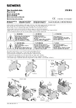
The type CM relay consists of two main current units
and their associated resistor and an indicating con-
tactor switch (ICS), or an ac indicating contactor
switch (ACS). The principal component parts of the
relay and their location are shown in figures 1 and 2.
2.1. MAIN UNIT
Each main unit has a pair of electromagnets operat-
ing on a single disc. The disc is damped by a perma-
nent magnet. Each disc carries its own set of
contacts with the two sets being connected in paral-
lel, in order that either disc may close the trip circuit.
The electromagnet pair are mounted face to face on
opposite sides of the disc, and so connected that the
electrical torque of one electromagnet opposes that
of the other, thus producing balanced operating
torque on the disc when the magnitudes of the cur-
rents through each of the two electromagnets are
equal. One of the electromagnets on the lower disc is
connected in series with one of the electromagnets
on the upper disc. Thus phase A current may balance
phase B current on the upper disc, and phase B cur-
rent balance C current on the lower disc. Conse-
quently with balanced system conditions, no
operating torque is produced on the two discs, but
with unbalanced conditions or an open phase the bal-
ance on the disc is upset and one or two sets of con-
tacts close.
Each electromagnet has a main coil located on the
center leg of an “E” type laminated structure that pro-
duces a flux which divides and returns through the
outer legs. A shading coil located on one of the outer
legs of the “E” structure causes the flux through that
leg to lag the main pole flux. The out-of-phase fluxes
thus produced in the air gap will cause disc rotation.
A resistor located to the rear of each main unit is
used as an aid in balancing the opposing torques by
controlling the current flow through the shading coils.
For some CM relays, the front electromagnet may
have adjustable plugs which are used to aid in cali-
bration.
41-181.2K
Effective:
June 1980
Supersedes I.L. 41-181.2J, dated March 1978
( | ) Denotes Change Since Previous Issue
Type CM Phase
Balance Current Relay