


P50 Agile P153
7 Protection Parameter Settings
P153/EN M/B
7-17
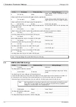
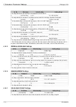
Sr. No
Parameter
Default setting
Setting Range
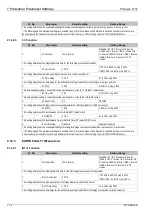
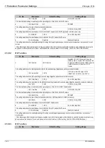
2.
tclp Time Delay
7200 S
0 to 14400s step 1s
This setting controls the period of time for which the relevant overcurrent and earth fault settings are altered or inhibited following circuit
breaker closure.
3.
I>1 Status
Enabled
Blocked / Enabled
The I>1 status cells have two setting options, "Enabled" and "Blocked". Selecting "Enabled" for a particular stage means that the current
and time settings programmed in the following cells will be adopted during the "tclp" time. Selecting "Blocked" simply blocks the relevant
protection stage during the "tclp" time. It also removes the following current and time settings for that stage from the menu.
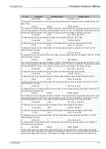
4.
I>1 Current Set
1.50*In
0.05 to 4.00*In step 0.01*In
This setting determines the new pick-up setting for first stage overcurrent element during the tclp time delay.
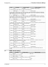
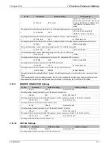
5.
I>1 Time Delay
0.01 S
0s to 100s step 0.01s
This setting determines the new operating time delay for the first stage definite time overcurrent element during the tclp time.
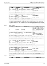
6.
I>1 TMS
0.100
0.025 to 1.2 in step 0.005
This setting determines the new time multiplier setting for the first stage element to adjust the operating time of the IEC / UK IDMT
characteristic during the tclp time.
7.
I>1 Time Dial
1
0.01 to 100 step 0.01
This setting determines the new time dial setting for the first stage overcurrent element to adjust the operating time of the IEEE / US IDMT
characteristic during the tclp time.
8.
I>2 Status
Enabled
Block / Enabled
The I>2 status cells have two setting options, "Enabled" and "Blocked". Selecting "Enabled" for a particular stage means that the current
and time settings programmed in the following cells will be adopted during the "tclp" time. Selecting "Blocked" simply blocks the relevant
protection stage during the "tclp" time. It also removes the following current and time settings for that stage from the menu.
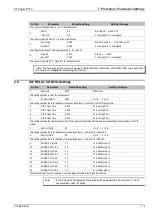
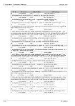
9.
I>2 Current Set
1.50*In
0.05 to 4.00*In step 0.01*In
This setting determines the new pick-up setting for second stage overcurrent element during the tclp time delay.
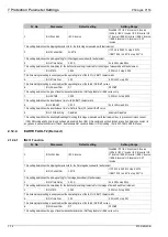
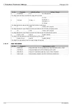
10.
I>2 Time Delay
0.01 S
0s to 100s step 0.01s
This setting determines the new operating time delay for the second stage definite time overcurrent element during the tclp time.
11.
I>2 TMS
0.100
0.025 to 1.2 step 0.005
This setting determines the new time multiplier setting for the second stage element to adjust the operating time of the IEC / UK IDMT
characteristic during the tclp time.
12.
I>2 Time Dial
1
0.01 to 100 step 0.01
This setting determines the new time dial setting for the second stage overcurrent element to adjust the operating time of the IEEE / US
IDMT characteristic during the tclp time
13.
I>3 Status
Enabled
Blocked / Enabled
The I>3 status cells have two setting options, "Enabled" and "Blocked". Selecting "Enabled" for a particular stage means that the current
and time settings programmed in the following cells will be adopted during the "tclp" time. Selecting "Block" simply blocks the relevant
protection stage during the "tclp" time. It also removes the following current and time settings for that stage from the menu
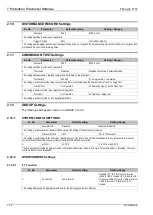
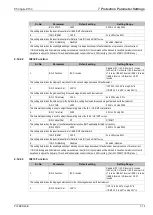
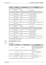
14.
I>3 Current Set
1.50*In
0.05 to 4.00*In step 0.01*In
This setting determines the new pick-up setting for third stage overcurrent element during the tclp time delay.
15.
I>3 Time Delay
0.01 S
0s to 100s step 0.01s
This setting determines the new operating time delay for the third stage definite time overcurrent element during the tclp time.
16.
I>3 TMS
0.100
0.025 to 1.2 step 0.005
This setting determines the new time multiplier setting for the third stage element to adjust the operating time of the IEC / UK IDMT
characteristic during the tclp time.
17.
I>3 Time Dial
1
0.01 to 100 step 0.01
This setting determines the new time dial setting for the third stage overcurrent element to adjust the operating time of the IEEE / US
IDMT characteristic during the tclp time
18.
IN1>1 Status
Enabled
Blocked / Enabled
The IN1>1 status cells have two setting options, "Enabled" and "Blocked". Selecting "Enabled" for a particular stage means that the
current and time settings programmed in the following cells will be adopted during the "tclp" time. Selecting "Blocked" simply blocks the
relevant protection stage during the "tclp" time. It also removes the following current and time settings for that stage from the menu.
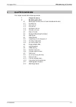
Summary of Contents for Agile P50 Series
Page 3: ...P50 Agile P153 1 Introduction P153 EN M B 1 1 INTRODUCTION CHAPTER 1...
Page 4: ...1 Introduction P50 Agile P153 1 2 P153 EN M B...
Page 10: ...1 Introduction P50 Agile P153 1 8 P153 EN M B...
Page 11: ...P50 Agile P153 2 Safety Information P153 EN M A 2 1 SAFETY INFORMATION CHAPTER 2...
Page 22: ...Chapter 2 Safety Information P50 Agile P153 2 12 P153 EN M A...
Page 23: ...P50 Agile P153 3 Hardware Design P153 EN M B 3 1 HARDWARE DESIGN CHAPTER 3...
Page 24: ...3 Hardware Design P50 Agile P153 3 2 P153 EN M B...
Page 32: ...3 Hardware Design P50 Agile P153 3 10 P153 EN M B...
Page 33: ...P50 Agile P153 4 Front Panel P153 EN M B 4 1 FRONT PANEL CHAPTER 4...
Page 34: ...4 Front Panel P50 Agile P153 4 2 P153 EN M B...
Page 39: ...P50 Agile P153 5 Configuration P153 EN M B 5 1 CONFIGURATION CHAPTER 5...
Page 40: ...P50 Agile P153 5 Configuration P153 EN M B 5 2...
Page 150: ...P50 Agile P153 5 Configuration P153 EN M B 5 112...
Page 151: ...P50 Agile P153 6 Protection Functions P153 EN M B 6 1 PROTECTION FUNCTIONS CHAPTER 6...
Page 152: ...6 Protection Functions P50 Agile P153 6 2 P153 EN M B...
Page 168: ...7 Protection Parameter Settings P50 Agile P153 7 2 P153 EN M B...
Page 189: ...P50 Agile P153 8 Monitoring Control P153 EN M B 8 1 MONITORING CONTROL CHAPTER 8...
Page 190: ...8 Monitoring Control P50 Agile P153 8 2 P153 EN M B...
Page 207: ...P50 Agile P153 9 SCADA Communications P153 EN M B 9 1 SCADA COMMUNICATIONS CHAPTER 9...
Page 208: ...12 SCADA Communications P50 Agile P153 9 2 P153 EN M B...
Page 220: ...12 SCADA Communications P50 Agile P153 9 14 P153 EN M B...
Page 221: ...P50 Agile P153 10 Installation P153 EN M B 10 1 INSTALLATION CHAPTER 10...
Page 222: ...10 Installation P50 Agile P153 10 2 P153 EN M B...
Page 234: ...13 Commissioning Instructions P50 Agile P153 13 2 P153 EN M B...
Page 242: ...12 Maintenance and Troubleshooting P50 Agile P153 12 2 P153 EN M B...
Page 250: ...12 Maintenance and Troubleshooting P50 Agile P153 12 10 P153 EN M B...
Page 252: ...13 Technical Specifications P50 Agile P153 13 2 P153 EN M B...
Page 263: ...P50 Agile P153 14 Wiring Diagrams P153 EN M B 14 1 WIRING DIAGRAMS CHAPTER 14...
Page 264: ...14 Wiring Diagrams P50 Agile P153 14 2 P153 EN M B...
Page 267: ......