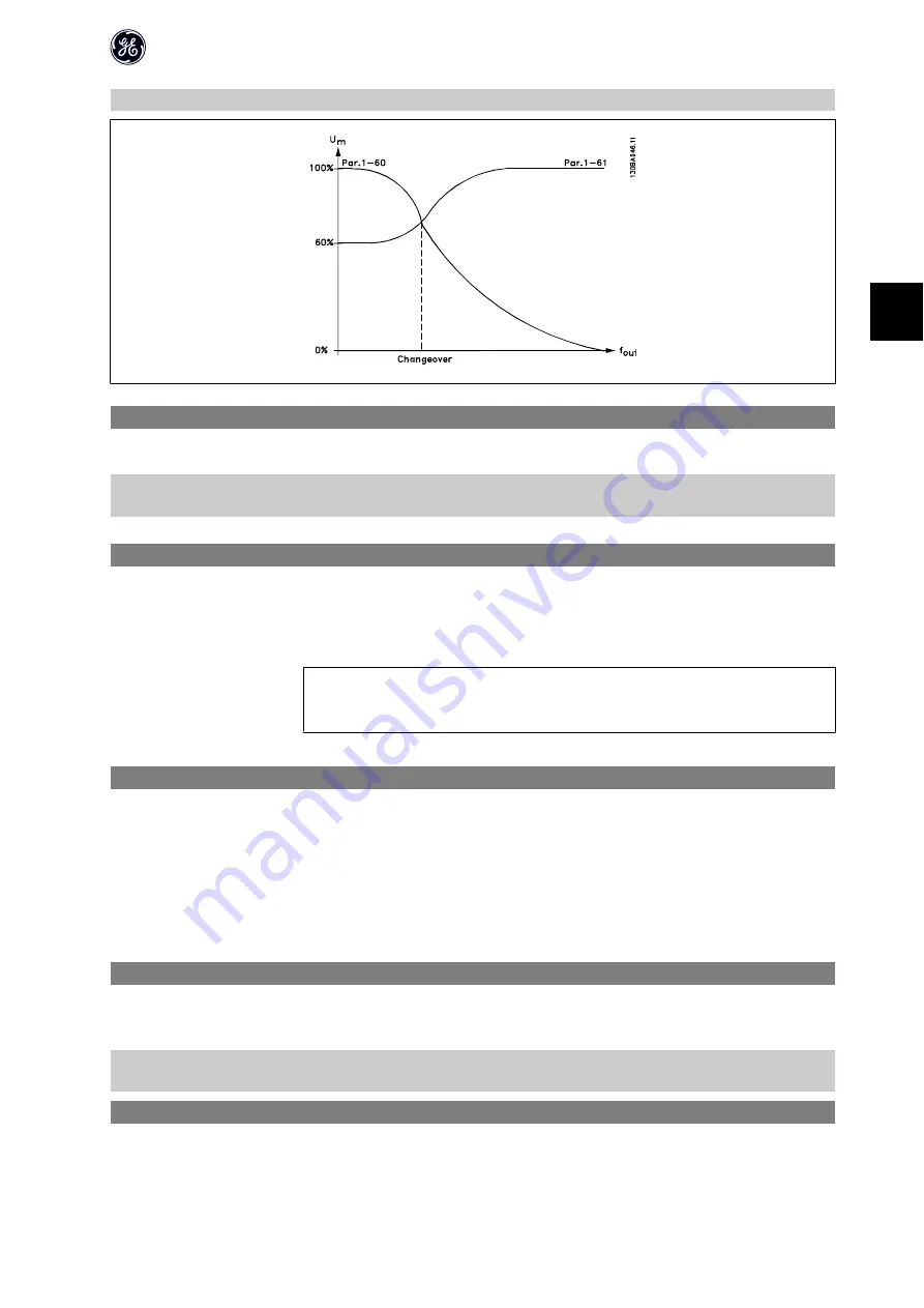
Change-over point is automatically calculated based on motor size.
1-61 High Speed Load Compensation
Range:
Function:
Use this parameter to obtain optimum load compensation when running at high speed.
100 %
*
[0 - 199 %]
Enter percentage to compensate in relation to load when motor runs at high speed.
Change-over point is automatically calculated based on motor size.
1-62 Slip Compensation
Range:
Function:
100 %
*
[-400 - 399 %]
Compensation for load dependent motor slip.
Slip compensation is calculated automatically based on rated motor speed, n
M,N
. Example: if par. 1-62 is set to 100%
and the 4 pole 1800 RPM motor has an actual nameplate RPM of 1750 RPM, then 50 RPM is added to the output
frequency by the drive.
NB!
This function is only active when par. 1-00,
Configuration Mode
, is set to
Speed Open Loop
[0], and when par. 1-01,
Motor Control Principle
, is set to
Advanced Vector Control
[1].
1-63 Slip Compensation Time
Range:
Function:
0.10 s [0.05 - 5.00 s]
Enter slip compensation reaction speed. A high value results in slow reaction whereas a low value results in quick
reaction.
If low-frequency resonance problems arise, use longer time setting.
4.2.5. 1-7* Start Adjustments
Considering the need for various start functions in different applications, it is possible to select a number of functions in this parameter group.
1-71 Start Delay
Range:
Function:
The start delay defines the time to pass from a start command is given until the motor starts accelerating.
Setting start delay to 0.0 sec. disables
Start Function
, [1-72], when start command is given.
0.0 s
*
[0.0 - 10.0 s]
Enter the time delay required before commencing acceleration.
Par. 1-72
Start Function
is active during
Start delay time
.
1-72 Start Function
Option:
Function:
[0]
DC Hold/Delay Time
Motor is energized with DC holding current (par. 2-00) during start delay time.
AF-60 LP™ Micro Drive Programming Guide
19
4


