Chapter 2
Connections and Controls
13
Time base correction is performed during digital capture. As a result, cameras do not require synchronization.
Audio Inputs and Output
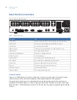
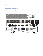
The unit is equipped with 4 audio inputs and 1 audio output. Both the audio output and the audio inputs are
line-level.The 4 audio inputs are associated with the first 4 cameras.
Note:
Line-level audio requires amplification.
Alarm Inputs
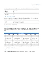
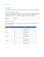
Four 8-pin connectors on the back panel provide the connections for the alarm inputs. Connect the wires to the
4 terminating connectors provided with the SymDec 16 plus 4. See the table below for a description of the
pinouts.
Note:
Do not attempt to wire any accessories directly to the I/O connector on the back panel. These connections require dry
contact (voltage free) closure to activate.
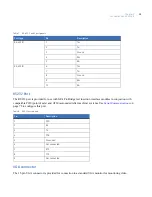
USB connectors
Industry compatible USB connectors for use with flashdrives for updating the SymDec 16 plus 4.
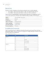
Cable
75-Ohm coaxial
Connectors
BNC
Auto terminating
Yes
Passive looping
Yes
Audio input
RCA jack, 315 mV, 40k Ohms. Unbalanced
Audio out
RCA jack, 315mV, 600 Ohms. Unbalanced
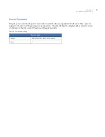
Table 5.
Alarm IN connector
Pin
Signal
Pin
Signal
Pin
Signal
Pin
Signal
1
Alarm Input 1 N/Open
5
Alarm Input 5 N/Open
9
Alarm Input 9 N/Open
13
Alarm Input 13 N/Open
C
Alarm Input 1 Common
C
Alarm Input 5 Common
C
Alarm Input 9 Common
C
Alarm Input 13Common
2
Alarm Input 2 N/Open
6
Alarm Input 6 N/Open
10
Alarm Input 10 N/Open
14
Alarm Input 14 N/Open
C
Alarm Input 2 Common
C
Alarm Input 6 Common
C
Alarm Input 10 Common
C
Alarm Input 14 Common
3
Alarm Input 3 N/Open
7
Alarm Input 7 N/Open
11
Alarm Input 11 N/Open
15
Alarm Input 15 N/Open
C
Alarm Input 3 Common
C
Alarm Input 7 Common
C
Alarm Input 11 Common
C
Alarm Input 15 Common
4
Alarm Input 4 N/Open
8
Alarm Input 8 N/Open
12
Alarm Input 12 N/Open
16
Alarm Input 16 N/Open
C
Alarm Input 4 Common
C
Alarm Input 8 Common
C
Alarm Input 12 Common
C
Alarm Input 16 Common
Summary of Contents for SymDec 16 plus 4
Page 1: ...SymDec 16 plus 4 User Manual ...
Page 10: ...SymDec 16 plus 4 User Manual x ...
Page 18: ...SymDec 16 plus 4 User Manual 8 ...
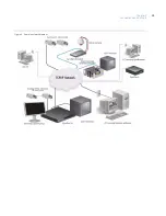
Page 29: ...Chapter 2 Connections and Controls 19 Figure 6 Sample network diagram ...
Page 99: ...Chapter 5 SymNav and SymBrowser 89 Figure 63 The SymNav main operation screen ...
Page 134: ...SymDec 16 plus 4 User Manual 124 ...
Page 144: ...SymDec 16 plus 4 User Manual 134 ...
Page 150: ...SymDec 16 plus 4 User Manual 140 ...


