GE Multilin
F35 Multiple Feeder Protection System
8-1
8 THEORY OF OPERATION
8.1 FAULT LOCATOR
8
8 THEORY OF OPERATION 8.1FAULT LOCATOR
8.1.1 FAULT TYPE DETERMINATION
Fault type determination is required for calculation of fault location – the algorithm uses the angle between the negative and
positive sequence components of the relay currents. To improve accuracy and speed of operation, the fault components of
the currents are used; that is, the pre-fault phasors are subtracted from the measured current phasors. In addition to the
angle relationships, certain extra checks are performed on magnitudes of the negative and zero-sequence currents.
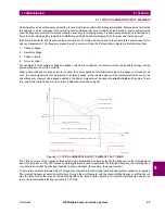
The single-ended fault location method assumes that the fault components of the currents supplied from the local (A) and
remote (B) systems are in phase. The figure below shows an equivalent system for fault location.
Figure 8–1: EQUIVALENT SYSTEM FOR FAULT LOCATION
The following equations hold true for this equivalent system.
(EQ 8.1)
where:
m
= sought pu distance to fault,
Z
= positive sequence impedance of the line.
The currents from the local and remote systems can be parted between their fault (F) and pre-fault load (pre) components:
(EQ 8.2)
and neglecting shunt parameters of the line:
(EQ 8.3)
Inserting the
I
A
and
I
B
equations into the
V
A
equation and solving for the fault resistance yields:
(EQ 8.4)
Assuming the fault components of the currents,
I
AF
and
I
BF
are in phase, and observing that the fault resistance, as imped-
ance, does not have any imaginary part gives:
(EQ 8.5)
where: Im() represents the imaginary part of a complex number. Solving the above equation for the unknown
m
creates the
following fault location algorithm:
(EQ 8.6)
where
*
denotes the complex conjugate and
.
Depending on the fault type, appropriate voltage and current signals are selected from the phase quantities before applying
the two equations above (the superscripts denote phases, the subscripts denote stations).
For AG faults:
(EQ 8.7)
mZ
(1-m)Z
R
F
Z
A
Z
B
E
A
E
B
V
A
V
B
V
F
I
A
I
B
Local bus
Remote
bus
distance to fault
842780A1.CDR
V
A
m Z I
A
⋅ ⋅
R
F
I
A
I
B
+
(
)
⋅
+
=
I
A
I
AF
I
Apre
+
=
I
B
I
BF
I
Apre
–
=
R
F
V
A
m Z I
A
⋅ ⋅
–
I
AF
1
I
BF
I
AF
--------
+
⎝
⎠
⎛
⎞
⋅
-----------------------------------
=
Im
V
A
m Z I
A
⋅ ⋅
–
I
AF
-----------------------------------
⎝
⎠
⎛
⎞
0
=
m
Im
V
A
I
AF
∗
⋅
(
)
Im
Z I
A
I
AF
∗
⋅
⋅
(
)
----------------------------------------
=
I
AF
I
A
I
Apre
–
=
V
A
V
A
A
=
,
I
A
I
A
A
K
0
I
0
A
⋅
+
=
Summary of Contents for F35
Page 2: ......
Page 4: ......
Page 296: ...5 174 F35 Multiple Feeder Protection System GE Multilin 5 9 TESTING 5 SETTINGS 5 ...
Page 328: ...7 8 F35 Multiple Feeder Protection System GE Multilin 7 2 TARGETS 7 COMMANDS AND TARGETS 7 ...
Page 350: ...A 16 F35 Multiple Feeder Protection System GE Multilin A 1 PARAMETER LIST APPENDIXA A ...
Page 422: ...B 72 F35 Multiple Feeder Protection System GE Multilin B 4 MEMORY MAPPING APPENDIXB B ...
Page 472: ...E 12 F35 Multiple Feeder Protection System GE Multilin E 2 DNP POINT LISTS APPENDIXE E ...


