6
EN
Multi Function Professional Puncher – A1
4. USER OPERATIONS
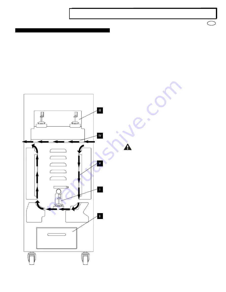
i.
Interchanging Die Sets:
Are completed without tools and only take seconds to perform
ii. Punch Chip Container:
Easy-to-access chip tray for quick chip disposal
iii. Die Set Storage:
Holds up to 2 spare Die Sets
iv. Punch Bypass:
Short straight-through paper path for unpunched documents
v. Punch Mode Path:
Wide radius turn can support stocks up to 300g/m
2
cover
Paper flow and User Interactive sections of Professional Puncher
A. Interchanging Die Sets:
Your Professional Puncher offers the convenience of interchangeable
die sets, allowing you to economically punch documents for a wide
variety of binding styles. Changing the machine's die sets is both quick
and easy, as the following instructions illustrate:
Note: For advanced Die Set Configuration instructions - See Section 8
Die Set User Manual.
Removing Die Sets from the Machine:
The inter-changeable die set
slot of the Professional Puncher is located above the bypass section of
the machine.
Step 1:
Stop the printer/copier.
Step 2:
Open the Professional Puncher access door panel.
Step 3:
Securely grasp the die lock handle and rotate it in the
CCW direction, as indicated in the label near the die lock handle.
This releases the die from the locked position.
Step 4:
Slide the die set out until it is fully removed, supporting it
with both hands.
Step 5:
Properly store the removed Die Set in the Die Set storage
area of the Professional Puncher (keep away from dust, dirt,
accidental falls from the edge of counters, etc.).
Step 6:
Select the desired Die Set for your new job and slide it into
the Die Set slot. Push the Die set firmly until the Die stop feature
contacts the round magnet. This is critical in ensuring the proper
position of the punch die set.
Step 7:
Grasp the handle and rotate it in CW direction until the
latch is fully engaged, as shown indicated in the label.
WARNING: POSSIBLE PINCH POINT HAZARD. WHEN
INSTALLING DIE SETS IN YOUR PROFESSIONAL
PUNCHER, ALWAYS KEEP FINGERS AND OTHER BODY
PARTS OUT OF THE MACHINE’S DIE SET SLOT AND
AWAY FROM ALL AREAS OF THE DIE SET, EXCEPT FOR
THE FINGER HOLE IN THE DIE SET. FAILURE TO FOLLOW
THESE PRECAUTIONS MAY RESULT IN INJURY.
Step 8:
Close the Access Door Panel.
Step 9:
Proceed with your printing and punching/creasing job.
Please note that when using a new die some oil will be present around
the punched holes on the sheet. After punching 25 to 50 sheets the die
will no longer leave oil on the sheets. It is recommended that a short
test print job be run after installing a new die or a die that has recently
been oiled.
B. Punch Chip Container:
The Punch Chip Container for your Professional Puncher is located at
the front of the machine’s base. The drawer should periodically be
pulled out and emptied. The Professional Puncher uses a sensor to
determine when the punch container is full. Once the punch container
becomes full the LCD display shows "Chip Tray Full" message and a
message also appear on the printers user interface screen.
Summary of Contents for A1
Page 93: ...93 RU Multi Function Professional Puncher A1 3 OK 4 5 1 2 3 Professional Puncher...
Page 97: ...97 RU Multi Function Professional Puncher A1 1 1 4 4 A 2 3 2 1 3 3 2 using 1 4 6 9 4 A 5...
Page 109: ...109 CHI Multi Function Professional Puncher A1 1 4 A 1 4 2 1 2 3 3 1 2 3 4 4 A 6 9 5...


