background image

GAT Access 6100 Terminal Series 


4


HB_GAT-ACCESS6100--EN_14 

www.gantner.com


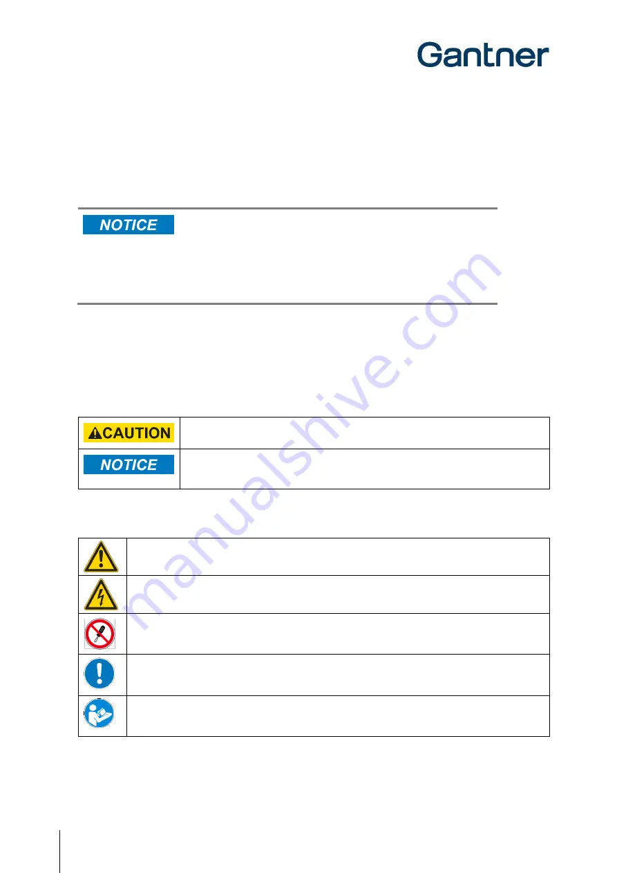
2. Property Damage Messages


Property damage messages are used to describe potentially hazardous situations that may lead to property damage. These 

messages have the same layout as safety messages but use the signal word "NOTICE" instead of “CAUTION”. 


Format of property damage messages that apply to an entire section:


Risk of damage to the device and connected devices 
Risk of malfunction 

- Read the following instructions carefully before installing the device. 

- Always adhere to the instructions. 


Format  of  property  damage  messages  that  are  embedded  in  text  and  apply  to  a  specific 
point: 

NOTE! 

Risk  of  damage  to  the  device  and  connected  devices.

  Read  the  following  instructions  carefully  before  installing  the 

device.


3. Definition of the Signal Words 


Indicates a hazardous situation that, if not avoided, may result in minor or moderate injury. 


Indicates information considered important, but not hazard-related (e.g., messages relating to 

property damage). 


4. Definition of the Safety Symbols


Caution: General Information 

This symbol indicates general warnings or cautions that are not related to a particular type of hazard. 


Caution: Electrical Shock 

This symbol indicates warnings related to electrical hazards (danger due to high voltage).


Prohibited: Do Not Disassemble 

This symbol indicates warnings about not disassembling certain components or equipment. Disassembling may 
lead to damage or malfunction of the device.


Mandatory Action: General Information 

This symbol indicates general information that must be read and followed before proceeding with the 
accompanying instructions. 


Mandatory Action: Read Instructions


This symbol indicates information referring to an important description in the manual, or other documentation, 
which must be read and followed.  


Summary of Contents for GAT ACCESS 6100

Page 1: ... EN_14 1 GAT Access 6100 Terminal Series Access Control and Shower Control Terminals Installation Commissioning Operation Document Version 1 4 GAT Access 6100 GAT Access 6100 F BIO GAT Access 6100 F Enrollment Station GAT TimeAxx 6150 ...

Page 2: ...in this manual shall depend exclusively on the conditions of the guarantee Any further reaching claims are excluded and in particular the manufacturer accepts no liability for the completeness or accuracy of the contents of this manual The right is reserved to make alterations and alterations may be made at any time without prior notice being given Trademarks Attention is drawn at this point to ma...

Page 3: ...ntended to inform the user about potentially hazardous situations or important information for the safe and proper use of the described product s The safety messages also include directives on how to avoid hazardous situations These safety messages and directives must be read and observed The structure of the safety messages and the meaning of the symbols used in this manual are described in this ...

Page 4: ...nal Words Indicates a hazardous situation that if not avoided may result in minor or moderate injury Indicates information considered important but not hazard related e g messages relating to property damage 4 Definition of the Safety Symbols Caution General Information This symbol indicates general warnings or cautions that are not related to a particular type of hazard Caution Electrical Shock T...

Page 5: ...f the product must be carried out in accordance with the technical conditions of operation as described in the corresponding documentation Therefore it is essential to read the corresponding chapter of this manual and observe the instructions and information therein If there are still some points that are not entirely clear please do not take a chance All queries can be clarified by your GANTNER r...

Page 6: ... INFORMATION U S A Note This equipment has been tested and found to comply with the limits for a Class B digital device pursuant to part 15 of the FCC Rules These limits are designed to provide reasonable protection against harmful interference in a residential installation This equipment generates uses and can radiate radio frequency energy and if not installed and used in accordance with the ins...

Page 7: ...ent Station 35 4 2 2 GAT Access 6100 GAT Access F BIO GAT TimeAxx6150 35 4 2 3 GAT Access 6100 F PoE 36 4 3 Network Connection 37 4 3 1 GAT Access 6100 GAT Access F BIO GAT TimeAxx6150 GAT Access F Enrollment Station 37 4 3 2 GAT Access 6100 F PoE 38 4 4 Input Output Connections 39 4 4 1 GAT Access 6100 GAT Access F BIO GAT TimeAxx6150 GAT Access F Enrollment Station 39 4 4 2 GAT Access 6100 F PoE...

Page 8: ...a GAT Access 6100 86 8 4 Which bit rates are used by a GAT Access 6100 for Ethernet and is this configurable 86 8 5 How can I set the date and time of a GAT Access 6100 86 8 6 How can I find the IP address of a GAT Access 6100 and change it 86 8 7 How can I find the MAC address of a GAT Access 6100 87 8 8 Setting IP address when MAC address is not known and IP address of the terminal is 0 0 0 0 87...

Page 9: ...00 EN_14 9 9 8 Fingerprint Reader 95 9 9 Housing 95 9 10 Ambient Conditions 95 9 11 Dimensions 96 9 11 1 GAT Access 6100 GAT Access 6100 F PoE 96 9 11 2 GAT Access 6100 F PoE 96 9 11 3 GAT Access 6100 F BIO 97 9 11 4 GAT Access 6100 F Enrollment Station 97 9 11 5 GAT TimeAxx 6150 98 ...

Page 10: ...GAT Access 6100 Terminal Series Table of Contents 10 HB_GAT ACCESS6100 EN_14 www gantner com ...

Page 11: ...iagrams and information required to install the GAT Access 6100 terminals Chapter 4 ELECTRICAL CONNECTIONS includes information on how to complete the power and network connections of the GAT Access 6100 Chapter 5 COMMISSIONING CONFIGURATION describes how to put the GAT Access 6100 into operation and includes how to configure the terminals using GAT Config Manager The main configuration settings a...

Page 12: ...ith example text is used in this manual to display important safety critical information that must be read and followed NOTE Following on from this signal word in the manual is a reference text that must be read and followed The reference text contains important information Non observance can lead to damage of the device or associated equipment Non Safety Critical Information The following formatt...

Page 13: ...ogy each terminal supports GAT Access 6100 B LEGIC prime GAT Access 6100 BA LEGIC advant GAT Access 6100 F MIFARE GAT Access 6100 ISO ISO 15693 GAT Access 6100 F PoE MIFARE GAT Access 6100 F BIO MIFARE GAT Access 6100 F Enrollment Station MIFARE GAT TimeAxx 6150 B LEGIC prime GAT TimeAxx 6150 F MIFARE GAT TimeAxx 6150 ISO ISO 15693 Supported Segments on Data Carriers The memory on a RFID data carr...

Page 14: ... turnstiles or gates that control the entry or exit to certain areas The access terminal checks the authorization of visitors and allows entry through an access point such as a turnstile or gate The terminal is designed to be wall mounted or integrated with a turnstile using the GAT Holder system It has a graphical LC display 4 function keys for configuration or user input on the front side an LED...

Page 15: ...eader GAT FR 055 8 Fingerprint sensor of GAT FR 055 9 Weather protection cover optional Figure 2 3 GAT Access 6100 F BIO The GAT Access 6100 F Enrollment Station is located at a central location such as the reception desk of a leisure facility When visitors first register at the facility the device is used to scan the visitor s fingerprint s and to transmit the fingerprint data directly onto the v...

Page 16: ...o the illuminated round RFID scan field the GAT Access 6100 reads the information on the data carrier and sends the data over the network Ethernet to a server for evaluation The visitor s authorization is checked and a response returned to the GAT Access 6100 When access is granted the GAT Access 6100 activates a corresponding relay output that opens the connected turnstile or gate for a certain t...

Page 17: ...sends the information of a data carrier over the interface to the host computer and waits for an appropriate reaction from the host An exception is the GAT Access 6100 F Enrollment Station which usually operates in offline mode For instances where an error occurs or the communication is interrupted the GAT Access 6100 can switch into emergency mode or out of order mode depending on the configurati...

Page 18: ...GAT Access 6100 Terminal Series General Information 18 HB_GAT ACCESS6100 EN_14 www gantner com ...

Page 19: ...ion The GAT Access 6100 terminals can be mounted directly onto a flat surface such as a wall The device rear part attaches to the flat surface e g concrete wall using screws NOTE The GAT Access 6100 must not be mounted directly onto a metallic surface as this material can adversely affect the reading field so that the data carriers may not be read anymore When installing onto an uneven surface the...

Page 20: ...easurements Cable Inlets The housing of the GAT Access 6100 has cable inlets for either flush 1 or surface 2 mounted cabling For surface mounted cabling ensure that the cabling can still be inserted once the device rear part has been installed Otherwise run the cabling through the cable lead ins prior to mounting CAUTION The connection of the cabling must always be performed in a powerless state S...

Page 21: ...y aggressive detergents for cleaning Do not damage the socket contacts 2 Ensure that the orientation is correct and plug the connection cable into the socket on the device rear part 3 Clip the top of the device front part into the device rear part 4 Push the device front part forwards until it clicks into place on the rear part Opening the housing The device front part can only be opened and remov...

Page 22: ...for surface mounted cabling 4 Mounting holes 5 Mounting screws 6 Terminal attachment holes 7 Back box 8 Flush mounted cabling 9 Surface mounted cabling Figure 3 4 GAT Access 6100 F PoE installation measurements Cable Inlets The cabling can be flush or surface mounted Flush mounted cabling 8 is fed through the opening 2 in the mounting plate Surface mounted cabling 9 is laid into the guide slot 3 o...

Page 23: ...in the mounting plate and both hooks 12 of the mounting plate also lie in the holes of the GAT Access 6100 F PoE For surface mounted cabling ensure that the connection cable runs in the guide slot 9 on the rear of the GAT Access 6100 F PoE 2 Push the GAT Access 6100 F PoE downwards until the hook 11 locks into place in the housing of the GAT Access 6100 F PoE Ensure that the terminal is securely a...

Page 24: ...owing measurements Figure 3 7 Dimensions of GAT FR 055 rear part and mounting holes a Connection Cables The connection cables power supply network etc are run through the cable lead ins of the GAT FR 055 For flush mounted cabling 1 the connection cables are fed from behind via the back box For surface mounted cabling 2 the connection cables must lie in the cable duct on the rear part of the GAT FR...

Page 25: ...ways be performed in a powerless state See chapter 4 ELECTRICAL CONNECTIONS for more information Attaching the GAT Access 6100 F Front Part 1 Check the socket in the device rear part Any dirt dust and moisture must be removed to ensure the secure connection of the connection cable NOTE Only clean the device in a powerless state Do not use any aggressive detergents for cleaning Do not damage the so...

Page 26: ...opened with the supplied special tool With this the two catches on the bottom of the device can be unlocked in succession Figure 3 11 Opening the housing Maintenance The sensor field of the GAT FR 055 should be cleaned periodically to ensure that the fingerprint can be clearly scanned NOTE Always use a damp not wet smooth cloth to clean the sensor field Acrid detergents and sharp materials must no...

Page 27: ...m HB_GAT ACCESS6100 EN_14 27 3 6 GAT Access 6100 F Enrollment Station The GAT Access 6100 F Enrollment Station is mounted onto a stainless steel stand and placed directly onto a table or similar Figure 3 12 Dimensions of the GAT Access 6100 F Enrollment Station ...

Page 28: ...ll without any back box 3 7 1 Surface Mounting 1 Apply silicone around the cable entrance on the device rear part This is necessary to seal the housing after it is mounted onto the wall Apply the silicone on the slightly recessed area 1 around the cable entrance The amount of silicone must be sufficient to completely seal the cable entrance after mounting the device onto the wall 2 Attach the devi...

Page 29: ...e device rear part See chapter 4 ELECTRICAL CONNECTIONS for information on the pin assignment and electrical specifications 4 Insert the rubber seal 5 in the device rear part 5 Attach the device front part with the front print 7 using the four screws included with the GAT TimeAxx 6150 6 Ensure that the rubber seal is total enclosed around the housing ...

Page 30: ... latches without the need for screws 3 7 2 Flush Mounting For flush mounting of the GAT TimeAxx 6150 a box is included with the terminal The back box can also be ordered separately GAT TimeAxx 6150 UP Part No 532325 Using the back box the GAT TimeAxx 6150 can be installed in brickwork concrete and cavity walls a Installation in Brickwork Walls ...

Page 31: ... opening in the GAT TimeAxx 6150 rear part with silicone 1 see step 1 of section 3 7 1 Surface Mounting 5 Mount the GAT TimeAxx 6150 into the back box using three screws 2 see step 2 of section 3 7 1 Surface Mounting Ensure that the cable opening is completely sealed with the previously applied silicone 6 The remaining installation procedure is the same as described in section 3 7 1 Surface Mounti...

Page 32: ...Walls ATTENTION Humidity water must never be able to penetrate into the housing Ensure that the silicone applied step 1 of section 3 7 1 Surface Mounting completely seals the housing and that the rubber seal step 4 of 3 7 1 Surface Mounting is inserted correctly and completely seals the entire length of the housing c Installation in Cavity Walls e g Plasterboard Walls 1 Cut out a rectangular hole ...

Page 33: ...n section a Installation in Brickwork Walls ATTENTION Humidity water must never be able to penetrate into the housing Ensure that the silicone applied step 1 of section 3 7 1 Surface Mounting completely seals the housing and that the rubber seal step 4 of 3 7 1 Surface Mounting is inserted correctly and completely seals the entire length of the housing ...

Page 34: ...GAT Access 6100 Terminal Series Installation 34 HB_GAT ACCESS6100 EN_14 www gantner com ...

Page 35: ...ectrical installations where the GAT Access 6100 is being installed e g electrical connection only by suitably trained electricians material specifications and tools used Also observe the environmental operating conditions of the GAT Access 6100 4 2 Power Connection 4 2 1 GAT Access 6100 F Enrollment Station The GAT Access 6100 F Enrollment Station is delivered with its power supply already connec...

Page 36: ...nnection 4 2 3 GAT Access 6100 F PoE The GAT Access 6100 F PoE requires a nominal voltage of 48 VDC see technical data which can be supplied via an Ethernet switch with Power over Ethernet PoE capability or a separate PoE power supply e g GAT Midspan 1 Port Part No 702375 One Ethernet cable min CAT 5 supplies the terminal with its power and network requirements The Ethernet cable connects to the R...

Page 37: ...commended to connect each GAT Access 6100 to a separate switch or patch panel socket Figure 4 3 Ethernet network example 4 3 1 GAT Access 6100 GAT Access F BIO GAT TimeAxx6150 GAT Access F Enrollment Station For these GAT Access 6100 terminals the Ethernet cable connects to the TX TX RX RX screw terminals on the rear part as shown in Figure 4 4 No RJ45 plug is used The wires of the Ethernet cable ...

Page 38: ...nding on which Ethernet standard is used 568A 568B TX green white orange white TX green orange RX orange white green white RX orange green Figure 4 5 Wire termination colors for Ethernet cables 4 3 2 GAT Access 6100 F PoE For the GAT Access 6100 F PoE the Ethernet PoE cable connects to the RJ45 socket on the rear part of the GAT Access 6100 F PoE housing as shown in Figure 4 2 CAT 5 STP or higher ...

Page 39: ...ents as indicated in the technical data see 9 TECHNICAL DATA 4 4 1 GAT Access 6100 GAT Access F BIO GAT TimeAxx6150 GAT Access F Enrollment Station Figure 4 6 shows how the input output cabling is connected to the screw terminals on the rear part of the terminal and the general connection to a turnstile For specific information regarding the electrical connections of the turnstile or door being co...

Page 40: ... of connecting a GAT FR 055 Part No 557433 or GAT FR 055 FIU3k Part No 557534 fingerprint reader The fingerprint reader cable connects to the 4 pin socket on the rear part of the GAT Access 6100 F PoE as shown in Figure 4 8 See the GAT FR 055 datasheet for detailed information on installing and connecting a GAT FR 055 GAT FR 055 FIU3k Figure 4 8 Connection of a fingerprint reader to the GAT Access...

Page 41: ...r the GAT Access 6100 Enrollment Station Installation Cable between device rear part and front part connected to both parts Housing closed and sealed Power supply connected Interface connected Host server is running for online mode RFID Reader tested hold data carrier next to scan field Configuration Latest software installed in the GAT Access 6100 Network parameters set IP address network name su...

Page 42: ...GAT Access 6100 Terminal Series Electrical Connections 42 HB_GAT ACCESS6100 EN_14 www gantner com ...

Page 43: ...pes of GAT Access 6100 share the same start up procedure The initialization process starts after power is supplied to the terminal The GANTNER logo and the current software version BL Vers is displayed the status LEDs flash green and red alternately and the terminal searches for a connected network Figure 5 1 Initialization screen of the GAT Access 6100 The initialization process takes approximate...

Page 44: ... up The system settings can be changed via the service menu see 5 3 1 Service Menu of the GAT Access 6100 If the service menu is not opened i e if no action is performed at the terminal the GAT Access 6100 continues to start and then goes into idle mode The main screen is displayed and the reading center LED flashes blue Figure 5 3 Main screen example ...

Page 45: ...ion of the GAT Access 6100 While this display is shown the function keys on the front of the GAT Access 6100 must be pressed in the following sequence 1 1 4 4 2 3 Figure 5 4 Keys for activating the service menu 1 1 4 4 2 3 The service menu is shown Figure 5 5 Service menu of the GAT Access 6100 Navigation in the service menu is done by pressing the corresponding keys on the front of the housing Ge...

Page 46: ... This principle works for all the settings in the service menu The following settings can be made DHCP Set to on if a DHCP server is used in the network In this case the remaining settings IP address subnet mask gateway DNS will be set automatically by the DHCP server IP Address If no DHCP server is used for automatic IP assignment enter the IP address of the GAT Access 6100 Subnet Mask Definition...

Page 47: ...to the reading field is read and displayed Read Clear Authorization These menu items are only shown for LEGIC readers With these functions it is possible to display or clear the authorization data stored in the internal LEGIC reader 5 3 4 Date and Time Settings During operation the GAT Access 6100 shows the current time and date on the display It is important that these settings are correct To cha...

Page 48: ...change the number with the keys 1 and 2 The set contrast can be seen directly while changing the contrast value With Default the contrast value can be reset to the default value Confirm with key 4 OK 5 3 6 Restore Factory Settings With the menu item Factory Settings it is possible to reset the system settings to the default settings on delivery Figure 5 11 Factory Settings After restoring the fact...

Page 49: ... 6100 must be established by entering all the communication settings required for a manual connection Project configuration Creating a project where the GAT Access 6100 and its communication settings are defined once To configure the GAT Access 6100 the connection to the device can then be established by clicking the Configure device option in the project One project can contain several devices To...

Page 50: ...www gantner com Select the communication type Choose TCPIP then click Next Figure 5 13 Open device for direct configuration Wizard step 1 Enter the IP address and port number of the GAT Access 6100 then click Next Figure 5 14 Open device for direct configuration over TCP IP Wizard step 2 ...

Page 51: ...om the device Figure 5 16 Configuration window for the GAT Access 6100 The configuration settings of the GAT Access 6100 are organized into several categories The directory on the left 1 lists the different configuration categories Click on a category and the settings for this category can be viewed and adjusted in the field to the right 2 A short description of the setting is shown at the bottom ...

Page 52: ...oftware scans the network and displays a list of all connected GANTNER devices Select your GAT Access 6100 from the list Use device details such as the IP and MAC address to identify the correct device o The selected device is highlighted in blue as shown in Figure 5 18 Click on OK 2 in Figure 5 18 o The selected device is added to the Devices list 3 in Figure 5 18 Figure 5 18 Open a project for d...

Page 53: ...T Access 6100 click on the Display Texts tab Here you can edit each individual display text for the selected GAT Access 6100 see 5 4 4 Display Texts To view and adjust the configuration settings of the GAT Access 6100 click on the 2 Configure button The existing configuration is uploaded from the GAT Access 6100 and displayed in the configuration window see Figure 5 16 ...

Page 54: ...er IPv4 Dynamic default gateway Default gateway got from the DHCP Server IPv4 100 MBit Ethernet enabled Enable 100 MBit Ethernet link 10 MBit if disabled Boolean true Protocol Terminal address Address of the device Integer 255 Type Protocol type Text Leisure Communication mode Operation mode of the device Text Online Leisure Omron mode active Indicate if OMRON mode for online communication is enab...

Page 55: ... stored on their data carriers for verification Compatibility If the host responds to the Card_Ident Command with the state 0x00 the Verification process is started Compatibility Mode Selection Deactivated Data on Card Data on Data base Compatibility Number Fingers Number of different fingers usable for verification Integer 2 Site key Site key to read write fingerprint data from data carriers Hex ...

Page 56: ...s license is loaded the terminal allows the writing of data from the management software directly to the data carrier Boolean false Second Ident with Card With this option it will be allowed to confirm the second identification with the data carrier Boolean true Data handling Deny if Checkin failed Access denied if the LockerCheck In fails Boolean false Check validity date Checks site number and v...

Page 57: ... Block Number Block number of the third party segment Integer 0 Mask The block that is read from a data carrier is logical AND combined with this mask value and then compared with the Result value Hex 00000000FFFF FFFF000 Result If the value which results from logical AND combination of the read block data from the data carrier and the Mask value above matches the Result value access is granted He...

Page 58: ... for reading the third party data Selection Key A Key B Third party write key Write key to be used for writing the third party data Selection Key A Key B DESFire Options for reading of MIFARE DESFire D Key Set Key Set containing Keys for DESFire Read Write if invalid DESFire easy is used Hex Application ID DESFire application ID number Hex 012ABC Read Key Number Number of the read key Integer 1 Wr...

Page 59: ... display the entire text line The access terminals can only show signs of windows code page 1252 Western European 1251 Cyrillic and 1257 Baltic All other signs will be shown as on the display Definition of the texts Idle This text is shown during normal online operation mode to instruct the user to hold their data carrier next to the reading field PushButton Is shown when a key must be pressed by ...

Page 60: ... 6100 In Offline Emergency mode it is possible to read data from any block within any sector of a data carrier With a configurable mask the read data can be separated into relevant and non relevant data The check for access authorization in Offline Emergency mode is then done by comparing the relevant data with a predefined result value If the relevant data matches exactly the defined result value...

Page 61: ..._GAT ACCESS6100 EN_14 61 3 Enter the Offline License number into the configuration option Application General Device License 4 The configuration option Emergency Mode enabled must also be checked 5 Configure the ThirdParty data in the Application Data handling section as follows ...

Page 62: ...field Result The result of the AND calculation of the read data and the Mask value are compared with this Result value If both values match access is granted If not access is denied In the previous example the Mask value of 00000000FFFFFF000000 means that the first 4 bytes of the read data are not relevant Mask value is entered in hex i e 8 digits 4 bytes with all bits set to 0 The next 3 bytes ar...

Page 63: ...0 Enrollment Station is Offline Emergency Mode where the start screen is as shown in Figure 6 2 Figure 6 1 GAT Access 6100 start screen in standard Figure 6 2 Standard start screen of a GAT Access operating mode waiting for data carrier 6100 F Enrollment Station in Offline Mode The GAT Access 6100 communicates with a server host computer during operation and for configuration For this communicatio...

Page 64: ...tches to either out of operation mode or emergency mode depending on configuration 6 2 2 Emergency Mode Emergency mode can be enabled or disabled in the functionality settings of the GAT Access 6100 see 5 4 3 List of Configuration Settings If communication to the server host is lost the GAT Access 6100 switches to emergency mode In this mode the terminal only checks the site key of a data carrier ...

Page 65: ...hich are read by holding them next to the RFID scan field 4 of the internal antenna The LED of the scan field changes color accordingly to indicate different status information Additional status information is indicated via the 4 segment LED display above the display The GAT Access 6100 terminals also have a monochrome LC display to show user information The display language can be changed in the ...

Page 66: ...e data carrier information to the host for evaluation with the stored personal data If access to the restricted area is granted a command is sent to the GAT Access 6100 and the terminal will unlock the controlled door turnstile for the configured time The terminal indicates whether access is granted or denied as shown below Additionally the four segment LED display and the RFID scan field illumina...

Page 67: ...lashes green and two acoustic signals are emitted Figure 6 6 Information display if the user must press a key The user must press one of the four keys below the display to gain access otherwise access is denied 6 4 3 Problem when Writing to the Data Carrier If there was a problem when writing to the data carrier e g with the Locker Check In function a GAT Access 6100 will show the following messag...

Page 68: ... the visitor to put one of the fingers that is stored on their data carrier onto the fingerprint reader Only when the scanned fingerprint matches one of the fingerprints on the data carrier are the following authorization checks performed Otherwise access is denied The fingerprint verification function can be used for example for season tickets and provides security against the misuse of lost data...

Page 69: ...en is not shown and you can begin directly with step 2 2 Hold the visitor s data carrier next to the RFID scan field of the Enrollment Station First the display will briefly show Enrollment and then invite the visitor to put the first finger on the sensor The RFID scan field illuminates in blue and the fingerprint sensor in red 3 Remove the data carrier from the RFID scan field 4 The visitor must ...

Page 70: ...see chapter 6 6 4 Cleaning the Fingerprint Sensor 5 Once the fingerprint has been correctly scanned the visitor must remove their finger from the sensor and repeat step 3 using the same finger The fingerprint must be scanned correctly 3 times to ensure reliable data 6 Depending on the terminal configuration the enrollment station may ask to scan a second fingerprint Proceed to step 8 otherwise Inv...

Page 71: ...carrier must be read once more to save the data onto the data carrier Request for data carrier 9 Hold the user s data carrier next to the RFID scan field within 3 seconds The fingerprint data is written onto the data carrier and a message is displayed to confirm whether the action was successful or not Writing successful Error writing not successful ...

Page 72: ...ated Access can then be completed using the data carrier alone without the need to scan the fingerprint 1 Press the second button on the Enrollment Station The display shows the message Finger off 2 Hold the visitor data carrier next to the RFID scan field The fingerprints are deleted from the data carrier and the fingerprint verification is deactivated After 1 second the result is shown as follow...

Page 73: ...fy message is shown on the display 2 Depending on whether there is fingerprint data stored on the data carrier or not the following two options are possible a No fingerprint data saved on data carrier Hold the data carrier next to the RFID reading field The data carrier s access status will be signaled as shown in point 3 b Fingerprint data saved on data carrier Hold the data carrier next to the R...

Page 74: ...e enrollment station as follows Verification successful Error Verification not successful 6 6 4 Cleaning the Fingerprint Sensor The sensor surface should be regularly cleaned to guarantee a distinct and secure finger print identification NOTE Use a damp not wet soft cloth to clean the sensor Never use corrosive cleaning agents or sharp tools ...

Page 75: ...4 segment LED bar shines green to indicate that the equipment is available for use Figure 6 8 Information display of GAT TimeAxx 6150 in idle state In order to activate the equipment the user holds their data carrier next to the terminal s scan field The terminal sends the user s data to a server that checks the authorization of the user Depending on the system configuration a fee can be applied f...

Page 76: ...eld while the equipment is turned on and the terminal will turn off the equipment and pause the countdown The display indicates the paused state Figure 6 10 Pausing the equipment To reactivate the equipment the user again holds their data carrier next to the scan field In the configuration it is also possible to enable pausing of the countdown via the digital optocoupler input This allows the user...

Page 77: ... operation The GAT Access 6100 must communicate with a server host that decides if the data carrier is valid and if the controlled door or turnstile may be unlocked If the server host is not available or is not responding to the requests of the GAT Access 6100 the terminal will switch into the Emergency mode if configured In this mode the access terminal only reads the site key of the data carrier...

Page 78: ...the data carrier is held in front of the reading field until the locker check in process is complete If the data carrier is removed before the process is complete access is denied and the GAT Access 6100 displays the following message Figure 6 12 Information screen in Locker Check In mode In this case the data carrier must be read again by the terminal Access is granted only once the data carrier ...

Page 79: ... all other relays are configured to No function then only Relay 1 will be activated when an optocoupler set to External Release receives an input Alternatively if all the relays are configured to Entrance then all relays are activated when any optocoupler set to External Release receives an input An additional setting for the external release function allows access information to be sent to the ho...

Page 80: ...GAT Access 6100 Terminal Series Operation 80 HB_GAT ACCESS6100 EN_14 www gantner com ...

Page 81: ...ware GAT Config Manager is used to check for new firmware versions and to upload the update to the GANTNER device An internet connection is required to allow GAT Config Manager to connect to the GANTNER server and check for possible updates See the GAT Config Manager manual for detailed instructions on installing and operating GAT Config Manager See section 5 4 Configuration Settings for instructi...

Page 82: ...TNER server and returns a list of update packages Figure 7 2 Device update wizard If there is more than one update package available select the newest version and click Next A brief description of the changes included in the update is displayed when you mouse over the update package Figure 7 3 Select update version NOTE Ensure that there are no power or network interruptions during the update proc...

Page 83: ...100 This process usually takes around 1 2 minutes depending on this size of the update network speed etc Figure 7 4 Uploading file to GAT Access 6100 The update wizard displays the following message when the process is finished Click on Finish to close the wizard and return to the main page of GAT Config Manager Figure 7 5 Update process successfully completed ...

Page 84: ...GAT Access 6100 Terminal Series Updating the GAT Access 6100 84 HB_GAT ACCESS6100 EN_14 www gantner com ...

Page 85: ...T Config Manager This is done in three steps 1 Starting the device configuration wizard 2 Selecting the type of connection TCP IP with the following parameters Entering the IP address of the terminal Port number 8208 3 Start the configuration by pressing the button Start configuration In case the DHCP status is changed from OFF to ON the GAT Access 6100 will perform a reset If a relay has the func...

Page 86: ...it is possible to adjust date and time in different ways a With GAT Config Manager software see 5 4 Configuration Settings b Directly at the terminal in the Service mode see 5 3 System Settings c With the FUNLINE protocol command Set_Date and Set_Address d With the software GAT TimeSync which is part of the GAT SyncManager software 8 6 How can I find the IP address of a GAT Access 6100 and change ...

Page 87: ...al is 0 0 0 0 There are different possibilities a If DHCP is activated install a DCHP server b Restart the GAT Device Finder software and the GAT Access 6100 If DHCP is activated it is possible to select the MAC address of the GAT Access 6100 with the icon Add new Device and then set the desired IP address 8 9 Difference between Time and Delay in the Mode field for Locker Check In configuration Wi...

Page 88: ...online mode hold the authorization card SM100 or SAM 63 resp next to the scan field for approx 30 seconds b In the Service menu see 5 3 System Settings select Reader Read UID and then hold the authorization card SM100 or SAM 63 resp to the scan field for approx 30 seconds until the UID number is shown on the display c With the Enable_Authorisation command of the FUNLINE protocol see protocol manua...

Page 89: ..._Master Card_Ident Action_Started 8 16 Why does the GAT Access 6100 deny access with my data carrier in Emergency mode In emergency mode a GAT Access 6100 reads a certain segment LEGIC configurable MIFARE locker segment ISO 15693 general segment of the data carriers If the site key is correct same site key on data carrier and in the terminal access is granted otherwise the data carrier is rejected...

Page 90: ...O Pulse Time 300 Function Entrance Optocoupler 1 Function Entrance Event Trigger Falling Edge Fingerprint Verification Level 5 Mode Verification Deactivated Number Fingers 2 Site key 0 Display Contrast 10 General Time Format 0 24 Emergency Mode Enabled false Device License 0 Data Handling Deny if Checkin Failed false Check Validity Date false Locker 1 Read false Position on Card 4 Clear number fal...

Page 91: ...ng is stored in a defined position on the data carrier and if the data carrier has access permission The Offline License can be ordered from GANTNER Electronic GmbH The serial number and MAC address of the GAT Access 6100 is required and the license is valid only for one terminal To load the license into the GAT Access 6100 GAT Config Manager software from GANTNER Electronic GmbH is used see chapt...

Page 92: ...GAT Access 6100 Terminal Series Troubleshooting FAQ 92 HB_GAT ACCESS6100 EN_14 www gantner com ...

Page 93: ...wer Source power supply Average power consumption GAT Access 6100 GAT Access 6100 F BIO Enrollment Station GAT Access 6100 F PoE 3 W Full operation with sensor on 4 5 W Full operation with sensor off 3 5 W Power class 3 9 2 Reader Reader types GAT Access 6100 B GAT Access 6100 BA GAT Access 6100 ISO GAT Access 6100 F GAT Access 6100 F PoE GAT Access 6100 F BIO GAT Access 6100 F Enrollment Station ...

Page 94: ...ULow 2 VDC UHigh 6 VDC Input current 4 5 mA 9 6 Data Time Management Data storage Internal EEPROM memory for configuration and booking data Data preservation min 10 years Internal clock Quartz controlled real time clock Data preservation approx 12 h Gold Cap 9 7 Control Display Elements Control elements RFID reader 4 function keys Display elements Full graphic monochrome display LCD White LED back...

Page 95: ... FCC15 9 9 Housing Housing material Front part Rear part Stand of Enrollment Station Shockproof plastic PMMA Shockproof plastic PC ABS Aluminum Weight GAT Access 6100 BIO PoE GAT Access 6100 F Enrollment Station approx 0 3 kg approx 1 kg 9 10 Ambient Conditions Permitted ambient temperature GAT Access 6100 PoE GAT Access 6100 F BIO Enrollment Station 10 C to 55 C 10 C to 40 C Permitted storage tem...

Page 96: ...GAT Access 6100 Terminal Series Technical Data 96 HB_GAT ACCESS6100 EN_14 www gantner com 9 11 Dimensions 9 11 1 GAT Access 6100 GAT Access 6100 F PoE 9 11 2 GAT Access 6100 F PoE ...

Page 97: ...GAT Access 6100 Terminal Series Technical Data www gantner com HB_GAT ACCESS6100 EN_14 97 9 11 3 GAT Access 6100 F BIO 9 11 4 GAT Access 6100 F Enrollment Station ...

Page 98: ...ies Technical Data 98 HB_GAT ACCESS6100 EN_14 www gantner com 9 11 5 GAT TimeAxx 6150 _ _ Note This manual is valid as of March 14th 2019 It is subject to change Amendments and changes can be made without prior notice at any time ...

Page 99: ...4 16 T 61 29011 8114 info gantner com info gantner nl info aus gantner com London GB Bochum Germany Los Angeles USA T 44 1245 697588 T 49 234 58896 0 T 1 844 703 1139 info uk gantner com info de gantner com info us gantner com Ypern Belgium Dubai Middle East Ahmedabad India T 32 57 22 44 00 T 971 4 3333 466 info gantnerticketing com info gantner be info me gantner com Part No 332727 www gantner co...

Reviews: