


IF 632 Installation and Operation Manual
Release: 3 01/31/01
114
Card ID #
Each type of card is assigned a unique 8 bit code that the card transmits to the
CPU when it is polled. In operation each card is periodically polled and returns
its type code. The CPU detects if the card is functioning correctly, for a card type
at that location. Refer to Table L4, Card ID Type.
Card Location
Card No.
Card ID Type
Code
(hex value)
Card Description
Display Module
Card# 0
0C
Alphanumeric (LCD) display card
Bus Driver Module
Card# 4
01
Signal Circuits
Bus Driver Module
Card# 5
02
Relays
Bus
Driver
Module
Card#
6
05
Variety of features (city tie
supervision, ground fault, default
power supply supervision, +24 V,
+12V, +5V supervision, V-battery to
power supply, unregulated raw supply,
system on AC/Battery, Charging
Monitor, battery monitor, aux 1 & 2).
Analog Addressable
Module
Card# 17
09
XP95 analog addressable interface (1,
2 or 4 circuits)
Table L4, Typical Card ID Type
System Configuration
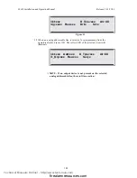
1. Select [1], the "Config" field.
2. Select “Display” [1], Press "
Enter
". (
Figure L-3 is an example of data shown
).
3. The alphanumeric screen will scroll and the user can view desired circuit.
4. Select “Download” [2] to download system configuration to a laptop
computer. Refer to IF 600 computer/laptop programming manual.
Card 00, ID# 0C is: A/N Panel
Card 04, ID# 01 is: CCM: 2 Sig Ckt, Class A
Card 05, ID# 02 is: CCM: 4 Rel Ckt
Card 06, ID# 05 is: CCM: City Tie, Buzzer etc.
Card 07, ID# 07 is: Unused
Card 17, ID# 09 is: Analog Addessable Interface
Figure L-3
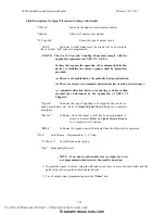
4. Press "
Enter
" key for previous menu. Figure L-2, is shown.
Technical Manuals Online! - http://www.tech-man.com
firealarmresources.com


