


Revision 14
164
August 02, 2019
8.4 Commonly Observed Problems
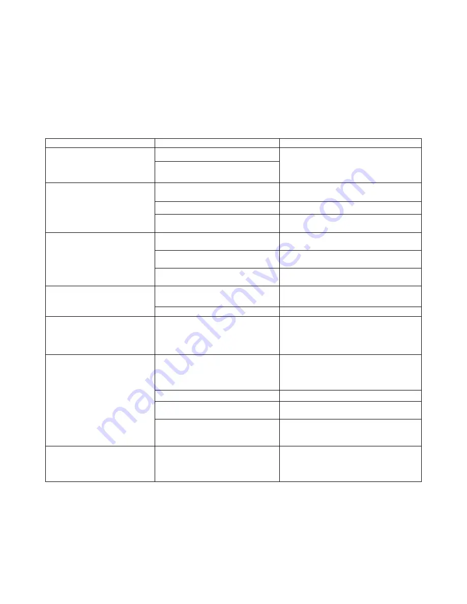
Table 8-2 is a list of commonly observed problems that may be encountered during normal
operation and servicing of the analyzer
Table 8-3: Troubleshooting Guide
Problem
Cause
Solution
1. Sensor Comm. Alarm
I.S. barrier channel blown.
Check DC voltage (Red & Black wires)
at bottom of Sensor block to be 10.5
volts for a Div1 unit and 24volts for a
Div 2 unit
Sensor block connector
unplugged or loose
2. Sensor Calibration Alarm Sensing tape is not installed.
Install sensing tape between sample
chamber and compression head.
Sample chamber is dirty.
Clean sample chamber.
Gas is running during the initial
start-up calibration
Perform Sensor Calibration on
unstained tape:
3. Tape movement Alarm
Tape is not installed over tape
counter capstan or tape is broken.
Check that Tape is path runs over the
tape counter capstan and is not broken
Tape capstan movement is
inhibited
Loosen set screw and move away from
plate.
IS barrier channel is blown
Check DC voltage (Red & Black wires)
at top of Sensor block to be 5 volts
4. Stain is not well defined
causing erratic readings.
Compression head not correctly
sealing.
Check the seal on the compression
head
Tape not seated properly
Remove tape and reinstall tape
5. Stain is uneven (darker at
top or bottom) causing erratic
readings.
Compression head not seated
properly.
Loosen screws that hold compression
head to chassis. Adjust compression
head so that it will sit flush against
sample chamber and check seal)
6. Stain is normal but
readings are still erratic.
Stains have too much overlap
Increase Tape Advance In Pulses
value in the Tape Box on the Global
tab of the GUI by 5 so that the stains
are further apart.
Back pressure on analyzer vent.
Check eductor for proper operation.
Frozen vent lines due to high
humidity in area.
Make sure vent slopes downward.
Sensor Current is too high. This
should be accompanied by a
Sensor Current alarm.
Lint in sample chamber causing light
blockage. Clean the sample chamber.
7. Stains overlapping each
other.
Insufficient pulses per tape
advance to allow correct stain
spacing.
Increase Tape Advance In Pulses
value in the Tape Box on the Global
tab of the application program by 5 so
that the stains are further apart.
Summary of Contents for ProTech903
Page 2: ......
Page 96: ...Revision 14 96 August 02 2019 Figure 5 19 Event Log...
Page 122: ...Revision 14 122 August 02 2019 Figure 5 38 Typical Modicon with Floating Point List...
Page 124: ...Revision 14 124 August 02 2019 Figure 5 40 Expanded Modbus Nodes...
Page 175: ...Revision 14 175 August 02 2019 Figure 9 17 Non Isolated 4 20 mA Inputs...
Page 190: ...Revision 14 190 August 02 2019...


