6 INSTALLATION OF VIDEO PLOTTER KIT
62
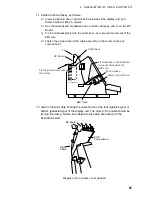
13. Attach the NH connector assy. (supplied) to the AIS cable and then connect
the NH connector to J4 on the RP Board.
20 mm
(1) Cut shrink tubing
in 20 mm lengths and
slip onto each wire.
(3) Heat shrink
tubing with
soldering iron.
Shrink tubing
(2) Solder connector
to signal cable.
Solder
HOW TO ATTACH NH CONNECTOR
RP BOARD
14P0371
RD-A > 1 >
RD-B > 2 >
GND > 5 >
FA-100 AIS TRANSPONDER
Junction Box
J4
FR/FAR-2805 series
Solder
Armor
*
*
* = Clamp armor
by cable clamp.
Use JIS cable TTYCS-4 or
equivalent. (See FA-100's
installation manual.)
Pair
Pair
25
26
27 GNDiso
TD-A
TD-B
14. Refasten the pcb compartment and the front panel.
15. Attach the top, right and left covers.
16. Attach key labels as below.
ORIGIN
VECTOR
TRUE/
REL
VECTOR
TIME
MARK
CHART
ALIGN
VIDEO
PLOT
NAV
MENU
AIS
DATA
AIS
MENU
AIS labels
Video plotter labels
Function keys
#1 #2 #3 #4
Summary of Contents for RP-340
Page 1: ...VIDEO PLOTTER RP 340...

