6 INSTALLATION OF VIDEO PLOTTER KIT
61
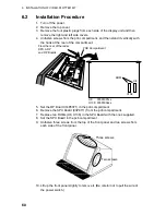
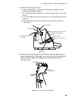
11. Install the M-card assy. as follows:
a) Insert the M-card assy. in its slot at the left side of the display unit, and
fasten it with two M4 x 8 screws.
b) Run the cable assembly between J2 on the M-card assy. and J1 on the RP
Board.
c) Fix the cable assembly with the cable tie so as to prevent movement of the
EMI core.
d) Fasten the ground wire of the cable assembly to the screw on the pcb
compartment.
Memory Card Drive
Cable Assy.
PCB
Compartment
No. 3
slot
RP Board
Fix the ground wire with
this screw.
EMI Core
J2
M-card Assy.
Fix cable assy. with cable tie
to prevent movement of
EMI core.
J1
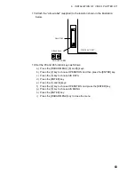
12. Lead in the AIS cable through the cable clamp at the rear (tabletop type) or
bottom (pedestal type) of the display unit. The armor of the cable should be
lying in the clamp. Fasten the cable with the cable clips shown in the
illustration below.
RP Board
PCB
Compartment
AIS
Cable
Display unit, top view, cover opened
Summary of Contents for RP-340
Page 1: ...VIDEO PLOTTER RP 340...

