2-29
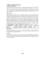
2.28 Power Supply Circuit (AC)
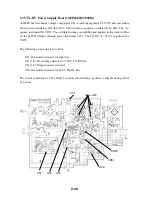
AC PWR Board (03P9245)
The PWR board contains a main-inverter, a sub-inverter, and protectors. The main-inverter
pr24 V and +32 V (for scanner motor), while the sub-inverter produces –12 V, +12 V,
+32 V, and +140 V from +24 V, output of the main-inverter. +5 V is generated by chopping
+24V. Power fail (P.F.) signal generator outputs “High” signal normally and “Low” signal
when the main-inverter fails. The RP data is backed-up when the P.F. signal is received. +24 V is
adjusted by VR51.
Main-inverter:
With the POWER switch pressed, +12 V regulator, Q1 turns on, and over-voltage and low-
voltage protector, relay drive circuit, and switching regulator controller are powered up. The
protector U1 activates when ship’s main is lower than 85 VAC and higher than 135 to 150 VAC.
If ship’s mains is higher than 135 to 150 VAC, the relay in the input line, K1 is turned off by the
signal from the protector U1, and no power is supplied to the main-inverter. The switching
frequency is adjusted by VR1. A rush current protector Q1 and R2 prevents rush current from
being flow into smoothing capacitors C11 and C12. When the smoothing capacitors are charged
to the rated voltage, the main inverter starts oscillating. The output of the T1 turns on triac Q1
and the R2 10 ohms, 5 W is short-circuited. Ship’s mains 110 VAC or 220 VAC is jumper
selectable as show in the table below. Smoothing capacitors C11 and C12 are charged by 100 to
170 VDC respectively. +5 V is generated from 24 V by a chopper IC.
Ship’s Mains
JP1
JP2
JP3
JP4
Fuse
110 VAC
Connected
Connected
Connected
Removed
10 A
220 VAC
Removed
Removed
Removed
Connected
5 A
Sub-inverter:
The sub-inverter produces –12 V, +12 V, +32 V, and +140 V from +24 V, output of the main-
inverter. These lines are not stabilized, but the +24 V line is stabilized by the main-inverter. The
switching frequency is adjusted by VR71.
Protector:
Over-current detector U91in the scanner motor power line (ANT MOTOR line) activates when
the current is 6 A or more for 0.8 seconds. The short circuit protector U72 operates when +140 V
line is short-circuited. The output from the U72 is latched by Q33 and then send to the switching
regulator controller U11.
Summary of Contents for FR-2155
Page 1: ...MARINE RADAR MODEL FR 2155 PRINTED IN JAPAN...
Page 3: ......
Page 4: ......
Page 5: ......
Page 65: ...3 9 Location of Parts on RP Board 14P0298 CR1 S1 Battery BT1 Flash ROM U3...
Page 80: ...3 24 Location of Parts on PFN 1 board 03P6668...
Page 86: ......
Page 107: ......
Page 108: ......
Page 109: ......
Page 110: ......
Page 111: ......
Page 112: ......
Page 113: ......
Page 114: ......
Page 115: ......
Page 116: ......
Page 117: ......
Page 118: ......
Page 119: ......
Page 121: ......
Page 122: ......
Page 123: ......
Page 124: ......
Page 125: ......
Page 126: ......
Page 127: ......
Page 128: ......
Page 129: ......
Page 130: ......
Page 131: ......
Page 132: ......
Page 133: ......
Page 134: ......
Page 135: ......
Page 136: ......
Page 137: ......
Page 138: ......
Page 139: ......
Page 140: ......
Page 141: ......
Page 142: ......
Page 143: ......
Page 144: ......
Page 145: ......
Page 146: ......
Page 147: ......
Page 148: ......
Page 149: ......
Page 150: ......
Page 151: ......
Page 152: ......

