2-10
Ant. Height
(menu selection)
Buffer
Q9
Mix
Q17
Gate
U87
Filter
Buffer
Q11, Q12
Gate
U56
One-shot
U35(Gate Array)
Inverter
Q28
Differential
Q27
Mix
Q46
Amp. &
Buffer
Q44, 55, 56
Peaking
Q26
Gain &
STC
Control
Q66, 67
STC Buffer
Q25, 52, 53
A/C RAIN
CR75
Buffer
Q65
Amp.
U93
D/A Conv.
U68
U35
STC VR Curve Generator
Q30, 32, 10, U92
STC in
A/C AUTO
mode
Q18
STC data
memory
0 to 5 V
TP12
TP11
0 to 5 V
TP9
SMPL T
GAIN: -7 to 0 V
A/C SEA: 0 to 5V
A/C AUTO
(From SPU Board)
R140
A/C AUTO : OFF
A/C AUTO : ON
*not used
A/C RAIN: -7 to 0 V
about
4 Vpp
about 4 Vpp
(Adjust by R140)
about 4.2 Vpp
3.5V
0
1us
2.7 Block Diagram of SPU Board (Video Amplifier)
VIDEO IN
Conv.
U100
Conv.
U100
TP13
STC Curve
Echo stretch
(range direction)
Q60~Q64
Gate
U54
Echo
stretch
on/off
U95
Amp.
Q35, Q37
Gain Cont.
Q34
Video
Contrast
Selector
U96
Log to Linear
Converter
CR57, 59, 71, 72
Amp.
Q13, 14, 21
Buffer
Q22, 23, 15
Gain Cont.
(short range)
Q19/20
*Gain reduced when
FTC is on.
*Noise is controlled and
gain lowered on ranges
up to 6 mile.
U43
RF VIDEO
(To AD Conv.)
TP4
QV VIDEO
(From ARPA Board:P551 C19)
FR2115-SME-10G
0 V
4.5 V
Range
High Antenna
Low Antenna
Antenna Height vs. STC Curve
0 V
4.5 V
Range
Sharp Curve (H)
Near STC Curve Selection
Gentle Curve (L)
Standard (M)
10 us
Video contrast
(menu selection)
about
4.0 Vpp
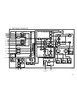
1) Mixer (Q17): In A/C AUTO mode, the pulse, whose level is the same as the main bang, is mixed with the video signal.
The falling edge of the pulse is coincident with the beginning of the video signal.
2) Mixer (Q46): The output of Q17 is amplified in reverse polarity by Q28, and at the same time, differentiated and then amplified by Q27.
The output of Q27 and Q28 is mixed so that the positive video signal without ac component is obtained.
Mixer eliminates the DC component of the video signal, or outputs the ac component of the video signal.
3) Peaking (Q26): not used. To improve range discrimination on short ranges, add capacitor C228, 56 to 100 pF on the SPU board.
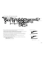
4) STC Curve: The STC curve is menu-selectable; "ANT HGT", INITIAL SETTING 1 and "CTR STC CURVE", INITIAL SETTING 4.
The latter is determined the STC curve near screen center, up to about 10 us.
5) STC in A/C AUTO mode (Q18): A/C AUTO works more effectively, compared with the FR-2100 series. Under heavy rain,
use AC AUTO rather than AC SEA, and reduce the gain setting.
6) Video constant (U96) : The video constant is selected in the initial setting 3 menu. Factory-setting is 3 for long range detection,
Under snow, rain, and heavy sea, select either 1 or 2.
1: Wide dynamic range. Similar echo to FR-2100.
2: Middle dynamic range.
3: Narrow dynamic range, but high visual intensity.
Figure 2.5 STC Curves
Selector
VIDEO
(To ARPA Board:P551 A18)
Summary of Contents for FR-2155
Page 1: ...MARINE RADAR MODEL FR 2155 PRINTED IN JAPAN...
Page 3: ......
Page 4: ......
Page 5: ......
Page 65: ...3 9 Location of Parts on RP Board 14P0298 CR1 S1 Battery BT1 Flash ROM U3...
Page 80: ...3 24 Location of Parts on PFN 1 board 03P6668...
Page 86: ......
Page 107: ......
Page 108: ......
Page 109: ......
Page 110: ......
Page 111: ......
Page 112: ......
Page 113: ......
Page 114: ......
Page 115: ......
Page 116: ......
Page 117: ......
Page 118: ......
Page 119: ......
Page 121: ......
Page 122: ......
Page 123: ......
Page 124: ......
Page 125: ......
Page 126: ......
Page 127: ......
Page 128: ......
Page 129: ......
Page 130: ......
Page 131: ......
Page 132: ......
Page 133: ......
Page 134: ......
Page 135: ......
Page 136: ......
Page 137: ......
Page 138: ......
Page 139: ......
Page 140: ......
Page 141: ......
Page 142: ......
Page 143: ......
Page 144: ......
Page 145: ......
Page 146: ......
Page 147: ......
Page 148: ......
Page 149: ......
Page 150: ......
Page 151: ......
Page 152: ......

