2-2
RX
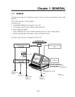
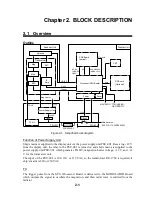
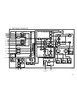
The 9.4 GHz echo signal received by the antenna is converted to 60 MHz signal by the MIC,
amplified by IF Amplifier, and fed to the SPU (Processor) Board as a video signal. It is digitally
processed and then displayed on the CRT. The SPU Board contains a video amplifier.
Auto Plotter (optional)
The following signals are applied from the SPU Board to the ARP-26 Board: Heading, Bearing
pulse, Video, Trigger, Bearing in AD format, and Ship’s speed in IEC-61162. Target acquision
and tracking are performed on the ARP Board, and displayed on the CRT. Target data includes
target position, CPA, TCPA, Speed, and Course.
Plotter (optional)
Data such as latitude and longitude in IEC-61162 format is delivered from the SPU Board to the
RP Board. Plotter data generated on the RP board is output to the SPU Board and processed to
display them on the screen. The plotter menu is generated on the SPU Board.
Summary of Contents for FR-2155
Page 1: ...MARINE RADAR MODEL FR 2155 PRINTED IN JAPAN...
Page 3: ......
Page 4: ......
Page 5: ......
Page 65: ...3 9 Location of Parts on RP Board 14P0298 CR1 S1 Battery BT1 Flash ROM U3...
Page 80: ...3 24 Location of Parts on PFN 1 board 03P6668...
Page 86: ......
Page 107: ......
Page 108: ......
Page 109: ......
Page 110: ......
Page 111: ......
Page 112: ......
Page 113: ......
Page 114: ......
Page 115: ......
Page 116: ......
Page 117: ......
Page 118: ......
Page 119: ......
Page 121: ......
Page 122: ......
Page 123: ......
Page 124: ......
Page 125: ......
Page 126: ......
Page 127: ......
Page 128: ......
Page 129: ......
Page 130: ......
Page 131: ......
Page 132: ......
Page 133: ......
Page 134: ......
Page 135: ......
Page 136: ......
Page 137: ......
Page 138: ......
Page 139: ......
Page 140: ......
Page 141: ......
Page 142: ......
Page 143: ......
Page 144: ......
Page 145: ......
Page 146: ......
Page 147: ......
Page 148: ......
Page 149: ......
Page 150: ......
Page 151: ......
Page 152: ......

