2-4
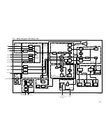
2.3 Function of Each Board (Display Unit)
Board Name
Function
SPU Board
03P9253
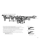
1) Contains a video amplitier circuit.
(a) Applies GAIN, STC, FTC and IR to video signal and outputs to the A/D converter.
(b) Adjusts video signal input level (adjusted by pot. VR140).
(c) Changes STC curve according to the antenna height set on the Radar menu.
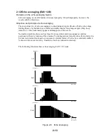
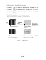
(d) Echo Stretching 1.
2) Performs A/D conversion of video signal.
3) Echo averaging (EAV 1/2/3)
4) Constructs radar picture from HD, BP, TRIG, and VIDEO signals.
5) Controls
keyboard.
6) Mixes data being fed from ARP and RP boards to display them on the screen.
7) Displays navigation data being fed from a navigator.
8) Reads and displays trackball, EBL, and VRM data.
9) Controls tuning circuit.
10) Outputs “degauss” signal to the DEGAUSS Board.
11) Outputs Tx trigger and pulselength signals to the antenna unit.
12) Backs up menu settings, radar map, tune voltage, tune Ind. voltage, and waypoint
with the EEPROM (U10).
13) Echo Stretching 2/3.
14) Generates menus and radar maps.
15) Echo trailling.
16) Checks for the presence of ARP and RP boards at power-up.
ARP Board
18P9002
1) Compatible with latest ARP-23 hardware.
2) Converts GAIN-, STC-, FTC-, and I/R-processed video signal to quantized video
(QV) and sends back to the SPU Board.
3) Performs automatic and manual target acquisition and tracking.
4) Detects HD, BP, TRIG, VIDEO, LOG and GYRO signal errors.
5) Calculates CPA and TCPA.
6) Detects land echo.
7) Outputs ARPA data to the SPU Board : Target No., R/B, CPA, TCPA, etc.
8) Processes
trial
maneuver.
RP Board
14P0298
1) Generates data (grid, own ship mark, mark, and ship's tracks, etc.) for the plotter
display.
2) Backs up data such as ship's tracks and marks.
3) Reads and displays digitized charts.
4) Outputs plotter display data to the SPU Board.
5) Inputs/outputs data (track, marks etc.) from/to the RAM card.
CARD I/F Board
14P0299
1) Receptacles of ROM and RAM cards.
2) Used to stores and retrieves data to/from ROM and RAM card.
INT Board
03P9252
1) Outputs HD, BP, TRIG and VIDEO signals to a radar slave display.
(J442/443, two output ports)
2) Receives HD, BP, TRIG and VIDEO signals from other radar. (J458)
3) Inputs/outputs RJ-7 signal. (J458/457)
4) Outputs ARPA data to the external equipment. (IEC-61162-2 , J454)
5) Outputs external buzzer signal. (J452)
6) Outputs V-SYNC, H-SYNC, R, G, B for a PC monitor or hard copier. A buffer circuit
required.
7) Inputs speed log signal, contact-closure. (J448)
8) Outputs alarm signals, Buffer board required.
Summary of Contents for FR-2155
Page 1: ...MARINE RADAR MODEL FR 2155 PRINTED IN JAPAN...
Page 3: ......
Page 4: ......
Page 5: ......
Page 65: ...3 9 Location of Parts on RP Board 14P0298 CR1 S1 Battery BT1 Flash ROM U3...
Page 80: ...3 24 Location of Parts on PFN 1 board 03P6668...
Page 86: ......
Page 107: ......
Page 108: ......
Page 109: ......
Page 110: ......
Page 111: ......
Page 112: ......
Page 113: ......
Page 114: ......
Page 115: ......
Page 116: ......
Page 117: ......
Page 118: ......
Page 119: ......
Page 121: ......
Page 122: ......
Page 123: ......
Page 124: ......
Page 125: ......
Page 126: ......
Page 127: ......
Page 128: ......
Page 129: ......
Page 130: ......
Page 131: ......
Page 132: ......
Page 133: ......
Page 134: ......
Page 135: ......
Page 136: ......
Page 137: ......
Page 138: ......
Page 139: ......
Page 140: ......
Page 141: ......
Page 142: ......
Page 143: ......
Page 144: ......
Page 145: ......
Page 146: ......
Page 147: ......
Page 148: ......
Page 149: ......
Page 150: ......
Page 151: ......
Page 152: ......

