2-12
2.9 Tuning Indication
The tuning indicator extends more than 80% of its full length on all ranges at best tuning. The
self-test result display reads the tune indicator voltage.
2.10 Manual Tuning
When tuning mode is changed from auto to manual mode, the tuning control voltage (a) found in
full search is selected. In manual tuning mode, the graphical tuning control voltage indicator
appears under the tuning indicator. The minimum scale is 2 V and the maximum scale is 32 V.
2.11 Tuning Circuit
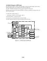
Figure below shows the tuning circuit. Tune control voltage is output from P551, A25 on the
SPU board.
Figure 2.7 Tuning Circuit
GA
U35
GA
U44
ENC-
ODER
U44
D/A
CONV.
B21
A25
U62
x1
F VT
0 to 5 V
#10
#8
#1
#3
x6
C VT #12
#14
U94
SUM
TUNE CONT.
(To MOTHER Board)
FR2115-SME-10B
P551
P551
U94
U94
B22
TUNE ENC A.
(From MOTHER Board)
TUNE ENC B.
Summary of Contents for FR-2155
Page 1: ...MARINE RADAR MODEL FR 2155 PRINTED IN JAPAN...
Page 3: ......
Page 4: ......
Page 5: ......
Page 65: ...3 9 Location of Parts on RP Board 14P0298 CR1 S1 Battery BT1 Flash ROM U3...
Page 80: ...3 24 Location of Parts on PFN 1 board 03P6668...
Page 86: ......
Page 107: ......
Page 108: ......
Page 109: ......
Page 110: ......
Page 111: ......
Page 112: ......
Page 113: ......
Page 114: ......
Page 115: ......
Page 116: ......
Page 117: ......
Page 118: ......
Page 119: ......
Page 121: ......
Page 122: ......
Page 123: ......
Page 124: ......
Page 125: ......
Page 126: ......
Page 127: ......
Page 128: ......
Page 129: ......
Page 130: ......
Page 131: ......
Page 132: ......
Page 133: ......
Page 134: ......
Page 135: ......
Page 136: ......
Page 137: ......
Page 138: ......
Page 139: ......
Page 140: ......
Page 141: ......
Page 142: ......
Page 143: ......
Page 144: ......
Page 145: ......
Page 146: ......
Page 147: ......
Page 148: ......
Page 149: ......
Page 150: ......
Page 151: ......
Page 152: ......


