background image

Yard/Customer            
Hull no.                 
Customer reference       
Order No.                
Document name            
Revision                 
Author                   
Date First Issue         
Comments                 

: ULSTEIN DESIGN & SOLUTION AS
: CO001/CO002
: U10662 - PX105
: 202121
: BRI-201041-01SI
: A
: HAB
: 06.05.2015
: A

Order Installation Manual

(5 of 7)

Summary of Contents for FA-150

Page 1: ...ull no Customer reference Order No Document name Revision Author Date First Issue Comments ULSTEIN DESIGN SOLUTION AS CO001 CO002 U10662 PX105 202121 BRI 201041 01SI A HAB 06 05 2015 A Order Installation Manual 5 of 7 ...

Page 2: ...This page left intentionally blank ...

Page 3: ...1 2 3 4 5 6 7 8 9 10 11 12 30 Navigation AIS 31 Navigation VDR 32 Navigation Bridge watch alarm system 33 Navigation Sound reception system ...

Page 4: ...This page left intentionally blank ...

Page 5: ...Revision history manual Rev A B C Description Date dd mm yyyy Sign A A 06 05 2015 HAB ...

Page 6: ...This page left intentionally blank ...

Page 7: ... data recorder_Furuno VR 7000 BRI D31003 01II A System Installation Manual pdf 2 BRI D32004 Bridge alarm system_UBAS 2 BRI D32004 01II D System Installation Manual pdf 3 BRI D32004 Bridge alarm system_UBAS 2 BRI D32004 01II D System Installation Manual pdf 4 BRI D33002 Sound reception_ VSS V2 BRI D33002 01II A System Installation Manual pdf ...

Page 8: ...This page left intentionally blank ...

Page 9: ...Index divider Section 1 N ...

Page 10: ......

Page 11: ...onflicts arising from unauthorized use shall be governed by the laws of Norway File Name BRI D30002 01II A System Installation Manual doc Page Page 1 of 1 Document Type SYSTEM INSTALLATION MANUAL Document name BRI D30002 01II Project Title Furuno FA 150 AIS Date First Issue 14 05 2013 Author FKO Revision A Enclosed documents from sub supplier revision history Revision A B C Description Enclosed do...

Page 12: ...PRINTED IN JAPAN UAIS TRANSPONDER FA 150 ...

Page 13: ... 2111 Fax Fax 0798 65 4200 0798 65 4200 FIRST EDITION FIRST EDITION NOV NOV 2004 2004 Printed in Japan Printed in Japan All rights reserved All rights reserved C1 C1 JUL JUL 14 2005 14 2005 Pub No Pub No IME 44310 C1 IME 44310 C1 00015008302 00015008302 00015008302 00015008302 TATA TATA FA 150 FA 150 0 0 0 1 5 0 0 8 3 0 2 0 0 0 1 5 0 0 8 3 0 2 IME44310C10 IME44310C10 IME44310C10 IME44310C10 I M E ...

Page 14: ...ge the equipment The voltage rating of the equipment appears on the label above the power connector ELECTRICAL SHOCK HAZARD Do not open the equipment unless totally familiar with electrical circuits and service manual Only qualified personnel should work inside the equipment CAUTION Observe the following compass safe distances to prevent interference to a magnetic compass Standard compass Steering...

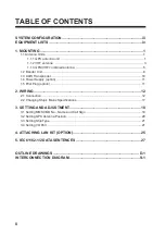
Page 15: ...nsponder 10 1 4 Power Supply option 11 1 5 Pilot Plug option 11 2 WIRING 12 2 1 Connection 12 2 2 Changing Ship s Mains Specifications 17 3 SETTING AND ADJUSTMENT 18 3 1 Setting MMSI IMO No Name and Call Sign 18 3 2 Setting GPS Antenna Position 20 3 3 Setting Ship Type 21 3 4 Setting I O Port 21 4 ATTACHING LAN KIT OPTION 25 5 IEC61162 1 2 DATA SENTENCES 27 OUTLINE DRAWINGS D 1 INTERCONNECTION DIA...

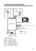
Page 16: ...T FA 1502 12 24 VDC UAIS TRANSPONDER FA 1501 External displ ay NAVNET2 Pil ot pl ug unit Sensor PC BEACON RECEIVER Al arm system UNIVERSAL AIS STATUS NAV FA 150 PWR DISP DIM MENU ENT LAN Category of the units GSC 001 Exposed to the weather GPA 017S Exposed to the weather GVA 100 Exposed to the weather FA 1501 Protected from the weather FA 1502 Protected from the weather DB 1 Protected from the wea...

Page 17: ...m CP24 00301 4 Coaxial cable TNC PS 3D 15 000 133 670 TNC TNC 15m 5 Mast mount fixture CP20 01111 004 365 780 For GSC 001 6 Right angle antenna base No 13 QA330 000 803 239 For GSC 001 7 L angle antenna base No 13 QA310 000 803 240 For GSC 001 8 Antenna base for rail mount No 13 RC5160 000 806 114 For GSC 001 9 Whip antenna FAB 151D 000 572 029 For Japan only 10 Antenna fixing bracket 4 310071 000...

Page 18: ...on of GPS satellite signal if the water freezes Extending antenna cable Three types of antenna cable extensions are optionally available a Antenna cable set CP20 02700 Antenna Unit Antenna Cable 30m 1 m Fabricate locally See next page N P 8DFB FA 1501 Connector Conversion Cable Assy NJ JP 3DXV 1 TNCP NJ 0 6m Waterproofing connector Wrap connector with vulcanizing tape and then vinyl tape Bind the ...

Page 19: ...um foil at four places 90 from one another Fold back aluminum foil onto shield and trim Expose the insulator by 1mm Expose the core by 5mm Slip the pin onto the conductor Solder them together through the hole on the pin Insert the pin into the shell Screw the clamp nut into the shell Tighten by turning the clamp nut Do not tighten by turning the shell Cover with heat shrink tubing and heat 30 10 C...

Page 20: ...nsmitting beam There should not be more than one antenna on the same plane The AIS VHF antenna should be mounted directly above or below the ship s primary VHF radiotelephone antenna with no horizontal separation and with a minimum of 2 8 meters vertical separation If it is located on the same plane as other antennas the distance apart should be at least 10 meters Cabling The cable should be kept ...

Page 21: ...sed attach the coaxial plug M P 7 dockyard supply as shown on the next page Horizontal separation distance More than 10 m More than 0 5 m More than 2 8 m Vertical separation distance Other VHF whip antenna Whip antenna for AIS GPS VHF combined antenna ...

Page 22: ...ion out of the radar beam The radar beam will obstruct or prevent reception of the GPS satellite signal There should be no interfering object within the line of sight to the satellites Objects within line of sight to a satellite for example a mast may block reception or prolong acquisition time Mount the antenna unit as high as possible Mounting it this way keeps it free of interfering objects and...

Page 23: ... vulcanizing tape and then vinyl tape for waterproofing 4 Insert the whip antenna from the top of the combined antenna 5 Secure the whip antenna with whip antenna fixture 6 Using a new plastic band supplied secure the cables and coaxial connector inside the antenna case 7 Mount the bottom cover 8 Fix the GPS VHF combined antenna to the ship s stanchion 40 to 50 mm diameter with antenna fixing brac...

Page 24: ...it and transponder unit is 1 m so locate the distributor unit within 1 m from the transponder unit Fix the distributor unit on the bulkhead facing the cable entrance downward Remove the lid of the distributor unit and secure the unit with two self tapping screws Self tapping screw 4x30 Note Be sure no foreign material or water enters the distributor unit ...

Page 25: ...nimal Keep the unit away from electromagnetic field generating equipment such as motor generator For maintenance and checking purposes leave sufficient space at the sides and rear of the unit and leave slack in cables Refer to the outline drawing A magnetic compass will be affected if the unit is placed too close to it Observe the following compass safe distances to prevent disturbance to the magn...

Page 26: ...ix the unit to the mounting location with four self tapping screws 5X20 S type Use the optional flush mount kit OP20 17 Name Type Code No Qty Fixing plate 20 007 2401 100 183 190 2 Hexagon head bolt M6X12 000 862 127 2 Wing bolt M4X30 000 804 799 4 Wing nut M4 000 863 306 4 Spring washer M6 000 864 260 2 1 Prepare a cutout in the mounting location whose dimensions are 167 W X 92 H mm 2 Insert the ...

Page 27: ...ocation should be well ventilated Mount the unit where shock and vibration are minimal Keep the unit away from electromagnetic field generating equipment such as motor generator For maintenance and checking purposes leave sufficient space at the sides and rear of the unit and leave slack in cables Refer to the outline drawing A magnetic compass will be affected if the unit is placed too close to i...

Page 28: ...t is placed too close to it Observe the following compass safe distances to prevent disturbance to the magnetic compass Steering compass 0 6 m Standard compass 0 9 m Fix the unit with four self tapping screws 4x16 to a desktop or the deck as shown in the figure below It is not necessary to open the cover 1 5 Pilot Plug option The pilot plug should be mounted near where the pilot steers the ship Th...

Page 29: ...C Connect to the al ternative power source 100 110 115 200 220 230 VAC Power Suppl y PR 240 CE DPYC 2 5 GPS VHF Conbined Antenna GVA 100 8 D FB CV 30 m 50 m Option RG 10U Y Local suppl y Standard Option Local Suppl y DPYC 1 5 0 6 m 0 8 m Ground is not req uired BREAKER 6 3A GPS ANT PC VHF ANT Other external device See next page Ground IV 2 0sq Transponder unit FA 1501 See page 14 12 24 VDC Monitor...

Page 30: ...1 Long range communication device Inmarsat C etc or External display Radar ECDIS Pilot plug COM2 COM3 External display NAVNET 2 Pilot plug COM4 COM6 GPS Gyrocompass Speedlog ROT etc Note A plastic sheet is placed across the cable glands of the transponder to keep out foreign material Cut out holes in the plastic where cables are to be lead in ...

Page 31: ...ector DPYC 2 5 TTYCS 1Q and TTYCS 4 are Japan Industry Standard cables Use them or the equivalents Conductor S 2 5 mm φ 2 01 mm 2 DPYC 2 5 Armor Sheath φ 12 8 mm Conductor S 0 75 mm φ 1 11 mm 2 TTYCS 1Q Four core twisted Armor Shield Sheath φ 11 3 mm Conductor S 0 75 mm φ 1 11 mm 2 TTYCS 4 Four twisted pairs Armor Shield Sheath φ 16 3 mm ...

Page 32: ...hield onto cable Lay in clamp where paint was removed L Depends on equipment connected Measure at the transponder Connection Procedures 1 Twist the cores 2 Press the terminal opener downward 3 Insert the wire to hole 4 Remove the terminal opener 5 Pull the wire to confirm that it is secure Terminal opener Wiring for WAGO connector WAGO connector Wire Twist Press downward ...

Page 33: ...16 Fabrication of power cable DPYC 2 5 40 mm Peel paint Taping Armor 50 mm 6 to7 mm Vinyl sheath Clamp here by cable clamp ...

Page 34: ... as below Attach label supplied as accessories to the punch mark on the front panel according to the ship s mains Ship s mains Tap connection Terminal board connection 1 2 100 115 VAC SEL 115 V b 200 230 VAC SEL 230 V a 1 2 3 4 5 6 7 8 Heat sink Tap connection Pull out to remove Front SEL 115 V SEL 230 V Top view Cover removed 1 2 3 100 115 VAC 1 2 3 200 230 VAC Terminal board connection a b White...

Page 35: ...USER SETTINGS INITIAL SETTINGS CHANNEL SETTINGS DIAGNOSTICS 2 Press ź on the cursor pad to choose INITIAL SETTINGS and press the ENT key The following password entry window appears ENTER PASSWORD Password entry window 3 Enter the password The INITIAL SETTINGS window appears Note that the password is known by only the FURUNO dealer INITIAL SETTINGS SET MMSI SET INT ANT POS SET EXT ANT POS SET SHIP ...

Page 36: ... IMO NO is selected 7 Press the ENT key and enter ship s IMO number in nine digits If the IMO number has 7 digits enter 0 twice followed by IMO number If the ship has no IMO number enter nine zeroes 8 Press the ENT key and the NAME is selected 9 Press the ENT key and enter ship s name using up to 20 alphanumeric characters 10 Press the ENT key and the C SIN is selected 11 Press the ENT key and ent...

Page 37: ...ion setting range 0 511 m 5 Press the ENT key and enter distance for location B C and D similar to how you did for A above B Distance from stern to GPS antenna position setting range 0 511 m C Distance from port to GPS antenna position setting range 0 63 m D Distance from starboard to GPS antenna position the setting range 0 63 m 6 Press the MENU key to return to the INITIAL SETTINGS menu 7 Press ...

Page 38: ...IG WIG Wing in ground 3 Vessel 4 HSC HSC High speed craft 5 Special craft 6 Passenger ships 7 Cargo ships 8 Tanker 9 Other type of ship For details see 1 5 Setting Up for Voyage on the operator s manual 3 Press the MENU key to save the setting 3 4 Setting I O Port Setting COM port PC port 1 In the INITIAL SETTINGS window press Ÿ or ź key to choose the SET I O PORT and press the ENT key SET I O POR...

Page 39: ...T key LONG RANGE Long range communication device for ex Inmarsat C EXT DISPLAY External display for ex Radar ECDIS Pilotplug etc DISABLE When the port is not used 7 Press the ENT key to display the SPEED setting window SET COM1 MODE LONG RANGE SPEED IEC 61162 2 IEC 61162 1 IEC 61162 2 QUIT MENU 8 Press Ÿ or ź to choose the data format or data transmission rate IEC61162 1 4800 bps IEC61162 2 38 4 K...

Page 40: ... No use IEC61162 2 HI LEVEL IF IEC61162 1 No use IEC61162 2 COM3 DISABLE SENSOR IEC61162 1 IEC61162 2 EXT DISPLAY IEC61162 1 IEC61162 2 COM4 DISABLE COM5 SENSOR IEC61162 1 IEC61162 2 COM6 SENSOR IEC61162 1 IEC61162 2 AD 10 STANDARD 4800bps 9600bps 19 2kbps 38 4kbps 57 6kbps MONITOR 4800bps 9600bps 19 2kbps 38 4kbps 57 6kbps SERVICE 4800bps 9600bps 19 2kbps 38 4kbps 57 6kbps BEACON 4800bps PC DISAB...

Page 41: ... No use IEC61162 2 HI LEVEL IF IEC61162 1 No use IEC61162 2 COM3 DISABLE SENSOR IEC61162 1 IEC61162 2 EXT DISPLAY IEC61162 1 IEC61162 2 COM4 DISABLE COM5 SENSOR IEC61162 1 IEC61162 2 COM6 SENSOR IEC61162 1 IEC61162 2 AD 10 STANDARD 4800bps 9600bps 19 2kbps 38 4kbps 57 6kbps MONITOR 4800bps 9600bps 19 2kbps 38 4kbps 57 6kbps SERVICE 4800bps 9600bps 19 2kbps 38 4kbps 57 6kbps BEACON 4800bps PC DISAB...

Page 42: ...emark 1 NET100 board 008 535 840 1 03P9332 2 Hex spacer 000 801 678 4 Attaching 1 Dismount the bottom cover 2 Attach NET100 board 03P9332 to the 24P0035 board referring to the figure shown below J9 03P9332 24P0035 Spacer Use screws removed at left figure NET Board03 Attaching 03P9332 J9 Unfasten 4 screw 24P0035 Transponder Bottem cover removed ...

Page 43: ...NT key STANDARD When connecting a LAN device MONITOR When connecting a monitor SERVICE Data output for service man DISABLE No connection 5 Press the ENT key enter IP address in the IP ADDRESS field and press the ENT key Setting range 000 000 000 000 to 255 255 255 255 Choose digit with Ż or Ź set value with Ÿ or ź 6 Press the ENT key enter sub net mask in the SUB NET MASK field and press the ENT k...

Page 44: ...800bps COM1 EXT DISPLAY Input Output IEC61162 2 38 4kbps IEC61162 1 4800bps COM2 EXT DISPLAY Input Output IEC61162 2 38 4kbps IEC61162 1 4800bps COM3 EXT DISPLAY Input Output IEC61162 2 38 4kbps IEC61162 1 4800bps SENSOR Input IEC61162 2 38 4kbps IEC61162 1 4800bps COM4 EXT DISPLAY Input Output IEC61162 2 38 4kbps IEC61162 1 4800bps COM5 SENSOR Input IEC61162 2 38 4kbps IEC61162 1 4800bps COM6 SEN...

Page 45: ...D AD 10 format Heading GBS GNSS satellite fault detection ROT Calculated value Rate of turn SSD UAIS ship static data Output data Sentences Sentence Contents AIVDM VHF data link message AIVDO UAIS VHF data link own vessel report AIABK UAIS addressed and binary broadcast acknowledgement AILRF AILR1 AILR2 AILR3 Long range function Long range reply with destination for function request A Long range r...

Page 46: ...TY 用途 備考 REMARKS 番 号 NO 型名 規格 DESCRIPTIONS 1 1 1 INSTALLATION MATERIALS 工事材料表 24AC X 9402 トラスタッピンネジ 1種 SELF TAPPING SCREW 5X20 SUS304 4 000 802 081 1 CODE NO 略図の寸法は 参考値です DIMENSIONS IN DRAWING FOR REFERENCE ONLY FURUNO ELECTRIC CO LTD 24AC X 9402 For FA 1501 A 1 ...

Page 47: ... 用途 備考 REMARKS 番 号 NO 型名 規格 DESCRIPTIONS 1 1 0 INSTALLATION MATERIALS 工事材料表 24AC X 9405 トラスタッピンネジ SELF TAPPING SCREW 5X20 SUS304 1種 クロ 4 000 802 840 1 CODE NO 略図の寸法は 参考値です DIMENSIONS IN DRAWING FOR REFERENCE ONLY FURUNO ELECTRIC CO LTD 24AC X 9405 For FA 1502 A 2 ...

Page 48: ...ONNECTOR N P 8DFB 座金付き 000 140 463 2 コンベックス PLASTIC BAND CV 200HT 000 809 226 2 アンテナ取付金具 ANTENNA FIXING BRACKET 24 003 3015 0 100 302 670 2 ミガキ平座金 FLAT WASHER M8 SUS304 000 864 130 4 六角ナット 1種 HEX NUT M8 SUS304 000 863 110 8 1 コ ド番号末尾の は 選択品の代表型式 コードを表します CODE NUMBER ENDING WITH INDICATES THE CODE NUMBER OF REPRESENTATIVE MATERIAL 略図の寸法は 参考値です DIMENSIONS IN DRAWING FOR REFERENCE ONLY 24AA X 985...

Page 49: ...TP 3DXV 1 1 000 123 809 1 CODE NO ビニールテープ VINYL TAPE NO360 0 2X19X10000 クロ エスロン 1 000 835 215 2 CODE NO コネクタ N CONNECTOR N P 8DFB 座金付き 2 000 140 463 3 CODE NO コネクタ CONNECTOR TNCP NJ 1 000 146 177 4 CODE NO 絶縁テープ SELF BONDING TAPE Uテープ 0 5X19X5M 1 000 800 985 5 CODE NO 略図の寸法は 参考値です DIMENSIONS IN DRAWING FOR REFERENCE ONLY FURUNO ELECTRIC CO LTD 24AC X 9403 For GPA 017S GSC 001 A 4 ...

Page 50: ... TY 用途 備考 REMARKS 番 号 NO 型名 規格 DESCRIPTIONS 1 1 0 INSTALLATION MATERIALS 工事材料表 24AA X 9404 ナベタッピンネジ SELF TAPPING SCREW 4X30 SUS304 1シュ 2 000 809 321 1 CODE NO 略図の寸法は 参考値です DIMENSIONS IN DRAWING FOR REFERENCE ONLY FURUNO ELECTRIC CO LTD 24AA X 9404 For DB 1 A 5 ...

Page 51: ... 名 称 NAME 数量 Q TY 用途 備考 REMARKS 番 号 NO 型名 規格 DESCRIPTIONS 1 1 0 ACCESSORIES 付属品表 24AC X 9501 保護カバー COVER 20 016 1091 2 1 100 297 032 1 CODE NO 略図の寸法は 参考値です DIMENSIONS IN DRAWING FOR REFERENCE ONLY FURUNO ELECTRIC CO LTD 24AC X 9501 For FA 1502 A 6 ...

Page 52: ...PARE WORKING QUANTITY REMARKS CODE NO BOX NO P SHIP NO SPARE PARTS LIST FOR U S E SETS PER VESSEL 0 TYPE NO 24AC X 9301 1 1 ヒューズ FGBO A 3A AC125V 2 FUSE 000 549 063 1 1 1 MFR S NAME FURUNO ELECTRIC CO LTD DWG NO 略図の寸法は 参考値です DIMENSIONS IN DRAWING FOR REFERENCE ONLY 24AC X 9301 For FA 1502 A 7 ...

Page 53: ...Antenna Cable Set CP20 02700 004 381 160 CP20 02710 004 381 170 A 8 ...

Page 54: ...Antenna cable Set CP24 00300 000 041 938 CP24 00310 000 041 939 A 9 ...

Page 55: ...Y Hatai D 1 ...

Page 56: ...Y Hatai D 2 ...

Page 57: ...Y Hatai D 3 ...

Page 58: ...Y Hatai D 4 ...

Page 59: ...Feb 19 03 D 5 ...

Page 60: ...May 20 03 D 6 ...

Page 61: ...Feb 22 05 D 7 ...

Page 62: ...Jan 9 03 D 8 ...

Page 63: ...Mar 11 04 H Hayashi D 9 ...

Page 64: ...Feb 02 05 D 10 ...

Page 65: ...Nov 28 03 D 11 ...

Page 66: ...Oct 02 03 D 12 ...

Page 67: ...H Hayashi Mar 10 05 D 13 ...

Page 68: ... 1 TTYCS 4 1 RS 232C CABLE DPYC 2 5 1 COM6 1 RD C AD DATA C COM6 1 RD H COM5 1 RD C COM5 1 RD H COM4 1 RD C COM4 1 RD H 4 4 4 4 4 4 TRANSPONDER UNIT COM4 JP COM4 JP COM4 2 RD B COM4 2 RD A COM4 TD B COM4 TD A GND ISO GND ISO COM1 JP DISP SW DISP SW GND ISO GND ISO COM1 JP COM1 RD B COM1 RD A COM1 TD B COM1 TD A ACK C ACK H ALM C ALM B ALM A AD CLK C AD CLK H AD DATA H COM6 JP COM6 JP COM6 2 RD B C...

Page 69: ...Index divider Section 2 N ...

Page 70: ......

Page 71: ... 01II A System Installation Manual doc Page Page 1 of 1 Document Type SYSTEM INSTALLATION MANUAL Document name BRI D31003 01II Project Title Furuno VR 7000 Voyage Data Recorder Date First Issue 27 08 2013 Author FKO Revision A Enclosed documents from sub supplier revision history Revision A B C Description Enclosed documents Date dd mm yyyy Sign A NO ENCLOSED DOCUMENTS 27 08 2013 FKO Component pic...

Page 72: ...This page left intentionally blank ...

Page 73: ... doc Page Page 1 of 56 Document Type SYSTEM INSTALLATION MANUAL Document name BRI D32004 01II Project Title Bridge Alarm System UBAS MkIV Date First Issue 28 02 2013 Author EKI Revision D Revision history Revision A B C Description Enclosed documents Date dd mm yyyy Sign A 30 07 2013 EKI B Changed to reduce component detail 23 04 2014 YLB Component picture Enclosed documents Description Enclosed d...

Page 74: ...UCTION 14 3 1 1 Scope of delivery 14 3 1 2 Technical data magicplex8 GIC Pro 14 3 1 3 Mountinf of magicplex8 GIC Pro 15 3 2 TERMINAL PIN ASSIGNMENT 16 3 2 1 Overview of terminal pin assignment Outside box 16 3 2 2 Overview terminal pin assignment at the terminal strip Inside box 17 3 2 3 Earthing of the box 17 3 2 4 Terminal pin assignment of the magicplex 8 GIC Pro 18 3 3 TALKER LISTENER CONNECTI...

Page 75: ...tten consent from ULSTEIN Any conflicts arising from unauthorized use shall be governed by the laws of Norway File Name BRI D32004 01II D System Installation Manual doc Page Page 3 of 56 5 1 1 Hardware Design 39 5 2 PREPARATORY MEASURES 41 5 2 1 Installing WAGO I O PRO 41 1 1 1 Starting Up the Ehernet Network 42 1 1 2 WAGO I O PRO CodeSys 46 2 2 4 Configure Hardware 46 2 2 5 Commissioning 50 WESTE...

Page 76: ...ation or publication of this document or its content is permitted without prior written consent from ULSTEIN Any conflicts arising from unauthorized use shall be governed by the laws of Norway File Name BRI D32004 01II D System Installation Manual doc Page Page 4 of 56 CABIN BUZZER 1 Buzzer Bedhead 10 tone Conslemount cutout 50X50mm Flushmount in standard electrical junction box Ø71mm ...

Page 77: ...l be treated as Confidential Information No use copying citation or publication of this document or its content is permitted without prior written consent from ULSTEIN Any conflicts arising from unauthorized use shall be governed by the laws of Norway File Name BRI D32004 01II D System Installation Manual doc Page Page 5 of 56 ...

Page 78: ...y and long life time are key pre requisites for the industry The product range combines state of the art display and computer technology with innovative features and options making it all that the integrator needs for top class type approved marine systems The high performance MMC Panel Computer models provide a wide choice of display size and format along with various processor and storage option...

Page 79: ...unauthorized use shall be governed by the laws of Norway File Name BRI D32004 01II D System Installation Manual doc Page Page 7 of 56 1 1 2 Labels and Locations Quality Control QC Label This label indicates that the unit is produced tested and packed according to manufacturer s QA specifications It will include a Personal ID and signature by the personnel responsible for approving the unit in prod...

Page 80: ...nces affect functionality and expected lifetime This must be considered during system assembly and installation Mounting position must carefully be selected to avoid any exposure of amplified vibration 2 2 2 General mounting instructions 3 In the area of the wheel house the distance of each electronics unit from the magnetic standard compass or the magnetic steering compass must not be less than t...

Page 81: ...area is recommended to be installed or mounted by suitable alignment or bulkhead deckhead mounting in such a way that reflections of light from the front pane of the display are not directed into the observer s viewing direction 3 The use of ordinary commercial filter plates or filter films is not permitted for items of equipment that require approval by optical effects aids of that kind can suppr...

Page 82: ...y File Name BRI D32004 01II D System Installation Manual doc Page Page 10 of 56 2 2 4 1 Physical Connections Terminal Label Markings of 13 inch unit Intel Atom CPU 2 2 4 2 DIGITAL OUPUT X1 DIG OUT Optional A mechanical and digitally driven Safety Signal Relay NO NC COM which allows the user via software to control external equipment that require or are compatible with the specifications If relay i...

Page 83: ...ed to 24V 12V works well between the input and 24 VDC the DIO0_GPI5 signal will go high To short circuit input and 24VDC works too as there is 12V on 24VDC Brief explanation for X1 DIG OUT HS1_OUT and DIO0_GP05 signals which are managed via software checks if the HS1 relay is on and thus the pin 1 HS1 and pin 2 OUT1 is connected DIO1_GPOU6 signal controls whether HS2 is on and thus pin 3 K3 and pi...

Page 84: ...ral types of gloves to control the unit 2 3 1 1 Light Sensor Used to sense level of ambient light in the surrounding environment The sensor data can be read by suitable software through the Hatteland Display SCOM functionality of the unit and thus can be used to control brightness remotely Note This sensor is not visible for the eye or has any illumination behind to indicate it s position Further ...

Page 85: ...dential Information No use copying citation or publication of this document or its content is permitted without prior written consent from ULSTEIN Any conflicts arising from unauthorized use shall be governed by the laws of Norway File Name BRI D32004 01II D System Installation Manual doc Page Page 13 of 56 2 4 Specifications HD 08T21 MMC xxx xxxx ...

Page 86: ...ease read these instructions carefully before use and make sure to use the system correctly and effeciently 3 1 1 Scope of delivery Table 1 Scope of delivery Quantity Name of the item 1 Software CD 1 Instruction manual 1 RJ45Cross over cable for configuration 1 Magicplex8 GIC Pro 10 Cable connection 10 Counter nuts 10 Locking caps 8 4 pole connecting plugs 2 2 pole connecting plugs 2 3 pole connec...

Page 87: ...thorized use shall be governed by the laws of Norway File Name BRI D32004 01II D System Installation Manual doc Page Page 15 of 56 3 1 3 Mountinf of magicplex8 GIC Pro 3 1 3 1 Dimension of the magicplex8 GIC Pro Figure 2 Mounting of the migcplex8 GIC Pro 3 1 3 2 Installation positions The magicplex8 GIC Pro fits for all installation positions Upright Hanging and Overhead It is advisable to install...

Page 88: ...C Pro Table 2 Overview of terminal pin assignment 1 PC output RS232 for configuration and readout of data 2 RJ45 network connector 3 USB connector for firmwire update NOTE For authorised technical staff only 4 Status LED See point 3 2 1 1 5 Reset button See point 3 2 1 2 3 2 1 1 Status LED The status LED indicates the magicplex8 GIC Pro s readiness for operation when it blinks Whenever the magiple...

Page 89: ...the terminal strip Table 3 Overview of terminal pin assignment 6 Power requirement 12 24 V DC Direct current plus und mass 7 8X RS422 TX RX TX RX 8 2X RS232 IN Input A B OUT Output A B Every output can be used with up to 10 listeners 2X RS232 TX Output to another device Max 2 5mm2 RX Input from another device Max 2 5mm2 GND Ground of the serial interface min 2 5mm2 Attention Ground for CH0 is the ...

Page 90: ... permitted without prior written consent from ULSTEIN Any conflicts arising from unauthorized use shall be governed by the laws of Norway File Name BRI D32004 01II D System Installation Manual doc Page Page 18 of 56 3 2 4 Terminal pin assignment of the magicplex 8 GIC Pro 3 2 4 1 Earthing in the box NOTE The channels CH0 CH1 CH6 and CH7 can be assigned both as input and output Not just 8 signals c...

Page 91: ...o use copying citation or publication of this document or its content is permitted without prior written consent from ULSTEIN Any conflicts arising from unauthorized use shall be governed by the laws of Norway File Name BRI D32004 01II D System Installation Manual doc Page Page 19 of 56 3 3 Talker Listener Connections Schema Figure 4 Talker Listener connections Schema ...

Page 92: ...the laws of Norway File Name BRI D32004 01II D System Installation Manual doc Page Page 20 of 56 3 4 Software configuration 3 4 1 Authentication When you starting software configuration you first have to log in Figure 5 Login Window The user name is Admin and the password configure 3 4 2 Device listing Figure 6 Device list The next window allows you to request the whole network about your current ...

Page 93: ... doc Page Page 21 of 56 Example Figure 7 Populated device listing On this example you can see a list being populated of two present multiplexers on the network represented by their hostname IP address Netmask and default gateway which is an optional settings and can be emplty By double clicking on a line of this list you can then enter the configuration of this specific multiplexer The settings of...

Page 94: ...92 168 2 175 You must enter it before being able to download a multiplexer configuration or upload one to it To be able to download or upload the configuration from to the multiplexer the compuer where the configuration software is excuted needs to be in the same subnet as the multiplexer With factory settings this means computer must have an IP address between 192 168 2 1 and 192 168 2 254 And di...

Page 95: ...10 Read firmware version By clicking this button the current version of the box firmware will be displayed in the field 17 11 Save configuration By using the save configuration button you case the actual settings of the magicplex8 on the computer 12 Download config By using the download config button you download the actual configuration from the box and take if over into the configuration softwar...

Page 96: ...uration function 3 4 5 Data validation Data validation is done before trying to change the network configuration If these controls fail then an information message is displayed and nothing happens The following controls take place The IP address must be of the form X X X X where X are numbers between 0 and 255 Additionnally the first number must be between 1 and 223 inclusive and different from 12...

Page 97: ... Change network configuration will send a message to the multiplexer to make it update its configuration The multiplexer should normally send a reply and reboot Figure 10 Network configuration NOTE As the system uses here multicast it can happen that the multiplexer does not reply After a few seconds you should see this window instead Figure 11 Network configuration This does not mean that the mod...

Page 98: ...he rest of the configuration If no connection to the multiplexer is possible after approximately 2 minutes then you get an error message Figure 13 Network configuration You should then check your network configuration and restart the configuration software Special case new subnet If you changed the IP address and or netmask of the multiplexer it can be that the multiplexer will not be anymore in y...

Page 99: ...clicking on the scroll down button you can chose between Off port is deactivated Line In port is fixed as input Line Out port is fixed as output Line In and Out port can work both input and output High Speed Line In 50 Hz port is fixed as input with a 50 Hz reading capability 2 Alias Name At this point it makes sense to enter the product name or the product type of the box which sends and or recei...

Page 100: ...imes makes sense to increase the size of the buffer to avoid unnecessary data loss failure recording The buffer can be changed between 5 and 60 The standard setting is 5 NOTE Data or signals of several inputs on one output lead to a so called bottle neck Please chose the number of inputs always in a meaningful way to avoid unnecessary failure recording This is when the data input is bigger than th...

Page 101: ...t communicate which port 0 or 1 is used as RS232 interface The basic setting is a set check mark this means the interface is defined as RS422 Figure 16 Port 0 und 1 as RS232 interface 3 4 9 Configuration of the magicplex8 GIC Pro magicplex8 GIC Pro Filters Filters are important characteristics to enhance the efficiency and performance of the multiplexer Especially when data are routed from a fast ...

Page 102: ...on of the magicplex8 GIC Pro magicplex8 GIC Pro Redundancy Redundancy enables you to receive data in order of priority which means that the ports of low priority are sleeping as long as the port of higher priority are receiving valid data A port is considered receiving no valid data if he receives No data within 2 seconds or Only invalid data within 2 seconds checksum is examined If you want to se...

Page 103: ... File Name BRI D32004 01II D System Installation Manual doc Page Page 31 of 56 If ports of higher priority get data again here PortO the settings get automatically back to the port of highest priority receiving valid data To enable Redundancy check the On Off checkbox 1 Set the backup port number in the field 2 If you want to define filters check the checkbox Sentences on off 3 then type the filte...

Page 104: ...parameters on this screen will be ignored 2 Protocol Here you can choose what kind of protocol you want to use for the port between UDP Multicast and TCP 3 Type Here you can choose what type of port it will be between Reader Writer and Server Note that if you chose the UDP protocol you can not choose the Server type 4 Broadcast Only usable if you chose UDP Reader or UDP Writer Check it if you want...

Page 105: ...multicast group for destination if you chose Writer several multicast groups as input if you chose Reader and both of them if you chose server The destination group is to be entered in field 8 The input groups have to be entered in field 9 NOTE Using the Multicast Server type will disable the logging functionality 10 Destinations This part is only enabled if the port is defined as reader or server...

Page 106: ... use copying citation or publication of this document or its content is permitted without prior written consent from ULSTEIN Any conflicts arising from unauthorized use shall be governed by the laws of Norway File Name BRI D32004 01II D System Installation Manual doc Page Page 34 of 56 Motion sensor 4 Motion sensor 4 1 1 Motion sensor adjustment Figure 1 Motion sensor ...

Page 107: ...mounted at least 2 meters apart D The motion sensor cover area shall only be available in positions on the bridge giving proper look out Find more information about settings in chapter 11 4 1 3 Installation considerations A 1 General Follow requirements in IMO resolution MSC 128 75 concerning the installation of the BNWAS A 2 Location of reset function 128 A4 1 3 1 It shall not be possible to init...

Page 108: ...o 5 seconds Alarm Indication LED glows red for 1 3 to 5 seconds if both detectors trip MOUNTING Height Up to 3 6 m 12 ft Room Size 8 12 m 24 40 ft in the FAR position 2 8 m 6 24 ft in the NEAR position Bracket Adjustment 20 downward 20 left and right Installation Options Surface or corner without bracket surface or ceiling with bracket ENVIRONMENTAL RFI Protection 30 V m up to 1000 MHz Operating T...

Page 109: ...lk test detection Flashing green PIR walk test detection Steady red 5 s Alarm MW PIR detection Flashing red and green alternately Trouble or masking is being detected by the self test circuitry Initial warm up routine stops 60 seconds after power up Notes During walk testing the green light glows steadily MW detection or flashes PIR detection depending on which one of the two detectors discovered ...

Page 110: ...tial Information No use copying citation or publication of this document or its content is permitted without prior written consent from ULSTEIN Any conflicts arising from unauthorized use shall be governed by the laws of Norway File Name BRI D32004 01II D System Installation Manual doc Page Page 38 of 56 Installation hints Figure 3 Installation hints ...

Page 111: ...Hardware Design Position I O Module 1 PLC ETHERNET 750 880 2 Digital Input Module 750 400 3 Digital Output Module 750 501 4 End Module 750 600 NOTE Hardware must include end module 750 600 and an I O module Please note that your hardware setup must include at least one I O module and end module 750 600 behind the PLC to ensure the function of the internal data bus 5 1 1 1 Electric Connection The 2...

Page 112: ...Contacts Internal Bus 5 24 V 0 V CAGE CLAMP Connections System Supply Connect Devices Connecting a conductor to the CAGE CLAMP 6 CAGE CLAMP Connections Field Supply DC 24 V Connect Devices Connecting a conductor to the CAGE CLAMP 7 Power Jumper Contact 24 V DC Connect Devices Power Contacts Field Supply 8 Unlocking Lug Assembly Inserting and Removing Devices 9 CAGE CLAMP Connections Field Supply 0...

Page 113: ...nd application program are executed Activate program execution RUN The mode selector switch is located behind the cover flap see No 13 in the Figure 1 above Figure 2 Mode selector switch closed and open damper of the service port 5 2 Preparatory Measures 5 2 1 Installing WAGO I O PRO WAGO I O PRO is a programming and visualization tool for PLC programs This software is used to develop PLC applicat...

Page 114: ... ETHERNET network You must perform three steps to start up the network Determine the IP address of your PC and change it if required Assign an IP address to the SPS Test the ETHERNET link The description of these work steps can be found in the corresponding following sections 2 2 2 1 Determining the IP address of your PC and changing it if required The explanation below describes how you can deter...

Page 115: ...aws of Norway File Name BRI D32004 01II D System Installation Manual doc Page Page 43 of 56 Figure 5 Properties of your LAN network link IV Check whether the current IP address is set within the address range 192 168 1 1 to 192 168 1 254 If not change it accordingly Figure 6 Properties of the TCP IP Internet protocol 2 2 2 2 Assigning an IP address to the SPS I Set the bits in order using the 8 DI...

Page 116: ...age Page 44 of 56 II Restart the SPS after adjusting the address selection switch to apply the IP configuration changes To do this open the cover for the service interface and press the mode switch down Figure 8 Restarting the SPS via hardware reset 2 2 2 3 Testing the ETHERNET Link I To test the ETHERNET link open the command line interpreter by entering cmd at Start Execute under Windows Figure ...

Page 117: ... Command line interpreter with ping statistics 2 2 2 4 Installing the USB Driver The WAGO USB Service Cable Item No 750 923 provides easy communication with the WAGO software tools WAGO ETHERNET Settings WAGO I O CHECK 3 etc and with the IEC 61131 programming topology WAGO I O PRO Proceed as follows to install the USB driver I Start the network browser and open the web page www wago com You can do...

Page 118: ...anual doc Page Page 46 of 56 1 1 2 WAGO I O PRO CodeSys 2 kstart 750 088x Beschr eibung Teil 1 9 mod_1287494243131_21 doc 65739 34443 1 I Launch the WAGO I O PRO development environment II Select the PLC from the drop down list for the target system settings Figure 13 PLC drop down list III Click OK to confirm your target system settings Figure 14 Confirm target system settings example WAGO_750 88...

Page 119: ...ned by the laws of Norway File Name BRI D32004 01II D System Installation Manual doc Page Page 47 of 56 I For the hardware configuration double click PLC Configuration on the Resources tab Figure 16 Configure the hardware under Resources tab PLC Configuration The PLC Configuration dialog appears II In the PLC Configuration dialog select K Bus FIX 1 in the tree structure III Then right click to ope...

Page 120: ...consent from ULSTEIN Any conflicts arising from unauthorized use shall be governed by the laws of Norway File Name BRI D32004 01II D System Installation Manual doc Page Page 48 of 56 IV Click on the button in the I O Configurator dialog The Selected Modules dialog appears Figure 18 Configuration dialog Inputs Outputs button V In the left window select the I O modules based on your hardware setup a...

Page 121: ...permitted without prior written consent from ULSTEIN Any conflicts arising from unauthorized use shall be governed by the laws of Norway File Name BRI D32004 01II D System Installation Manual doc Page Page 49 of 56 VI Click OK to close the Selected Modules dialog VII Then assign variables to the digital input output modules in the right window of the I O Configurator Figure 20 Configuration dialog...

Page 122: ...orway File Name BRI D32004 01II D System Installation Manual doc Page Page 50 of 56 2 2 5 Commissioning This chapter describes step by step how to load your previously created WAGO I O PRO project into your PLC how to start program execution and how to create a boot project 2 2 5 1 Configuring a Communication Driver for an ETHERNET Link I To set up the communication driver for the ETHERNET connect...

Page 123: ...te a new communication channel The Communication Parameters New Channel dialog appears Figure 22 Communication Parameters Create communication channel III For an ETHERNET connection assign a name to the communication channel you just created in the Name input box here ETHERNETConnection as an example IV Then select the driver Tcp Ip 3S Tcp Ip driver V Click OK to confirm your entries Figure 23 Com...

Page 124: ...s Figure 24 Communication Parameters IP address 2 2 5 2 Configuring a Communication Driver for a USB Link I Connect the USB cable 750 923 to a USB port of your PC II Under Windows you can check which COM port of your PC has been assigned to the USB cable at Start Settings Control panel System The System Properties dialog appears III Here select the tab Hardware and click the button Device manager ...

Page 125: ...item in the WAGO I O PRO dialog under the Online menu The Communication Parameters dialog appears VI In the Communication Parameters dialog click the NEW button to create a new communication channel The Communication Parameters New Channel dialog appears Figure 26 Driver Serial RS 232 3S Serial RS 232 driver VII For a USB connection assign a name to the communication channel you just created in th...

Page 126: ... the Communication Parameters accordingly You can leave all other parameters Baudrate Parity Stop bits Motorola byteorder Flow Control and the gateway settings as they are XII Click OK to confirm your entries 2 2 5 3 Loading and Starting the Program I To load the program into your PLC click on the Login menu item in the WAGO I O PRO dialog under the Online menu II Then start program execution in t...

Page 127: ...mation No use copying citation or publication of this document or its content is permitted without prior written consent from ULSTEIN Any conflicts arising from unauthorized use shall be governed by the laws of Norway File Name BRI D32004 01II D System Installation Manual doc Page Page 55 of 56 WESTER MO 3 SDW 500 SERIES 3 1 Ratings and safety control drawing ...

Page 128: ... be treated as Confidential Information No use copying citation or publication of this document or its content is permitted without prior written consent from ULSTEIN Any conflicts arising from unauthorized use shall be governed by the laws of Norway File Name BRI D32004 01II D System Installation Manual doc Page Page 56 of 56 ...

Page 129: ...Index divider Section 3 N ...

Page 130: ......

Page 131: ... doc Page Page 1 of 56 Document Type SYSTEM INSTALLATION MANUAL Document name BRI D32004 01II Project Title Bridge Alarm System UBAS MkIV Date First Issue 28 02 2013 Author EKI Revision D Revision history Revision A B C Description Enclosed documents Date dd mm yyyy Sign A 30 07 2013 EKI B Changed to reduce component detail 23 04 2014 YLB Component picture Enclosed documents Description Enclosed d...

Page 132: ...UCTION 14 3 1 1 Scope of delivery 14 3 1 2 Technical data magicplex8 GIC Pro 14 3 1 3 Mountinf of magicplex8 GIC Pro 15 3 2 TERMINAL PIN ASSIGNMENT 16 3 2 1 Overview of terminal pin assignment Outside box 16 3 2 2 Overview terminal pin assignment at the terminal strip Inside box 17 3 2 3 Earthing of the box 17 3 2 4 Terminal pin assignment of the magicplex 8 GIC Pro 18 3 3 TALKER LISTENER CONNECTI...

Page 133: ...tten consent from ULSTEIN Any conflicts arising from unauthorized use shall be governed by the laws of Norway File Name BRI D32004 01II D System Installation Manual doc Page Page 3 of 56 5 1 1 Hardware Design 39 5 2 PREPARATORY MEASURES 41 5 2 1 Installing WAGO I O PRO 41 1 1 1 Starting Up the Ehernet Network 42 1 1 2 WAGO I O PRO CodeSys 46 2 2 4 Configure Hardware 46 2 2 5 Commissioning 50 WESTE...

Page 134: ...ation or publication of this document or its content is permitted without prior written consent from ULSTEIN Any conflicts arising from unauthorized use shall be governed by the laws of Norway File Name BRI D32004 01II D System Installation Manual doc Page Page 4 of 56 CABIN BUZZER 1 Buzzer Bedhead 10 tone Conslemount cutout 50X50mm Flushmount in standard electrical junction box Ø71mm ...

Page 135: ...l be treated as Confidential Information No use copying citation or publication of this document or its content is permitted without prior written consent from ULSTEIN Any conflicts arising from unauthorized use shall be governed by the laws of Norway File Name BRI D32004 01II D System Installation Manual doc Page Page 5 of 56 ...

Page 136: ...y and long life time are key pre requisites for the industry The product range combines state of the art display and computer technology with innovative features and options making it all that the integrator needs for top class type approved marine systems The high performance MMC Panel Computer models provide a wide choice of display size and format along with various processor and storage option...

Page 137: ...unauthorized use shall be governed by the laws of Norway File Name BRI D32004 01II D System Installation Manual doc Page Page 7 of 56 1 1 2 Labels and Locations Quality Control QC Label This label indicates that the unit is produced tested and packed according to manufacturer s QA specifications It will include a Personal ID and signature by the personnel responsible for approving the unit in prod...

Page 138: ...nces affect functionality and expected lifetime This must be considered during system assembly and installation Mounting position must carefully be selected to avoid any exposure of amplified vibration 2 2 2 General mounting instructions 3 In the area of the wheel house the distance of each electronics unit from the magnetic standard compass or the magnetic steering compass must not be less than t...

Page 139: ...area is recommended to be installed or mounted by suitable alignment or bulkhead deckhead mounting in such a way that reflections of light from the front pane of the display are not directed into the observer s viewing direction 3 The use of ordinary commercial filter plates or filter films is not permitted for items of equipment that require approval by optical effects aids of that kind can suppr...

Page 140: ...y File Name BRI D32004 01II D System Installation Manual doc Page Page 10 of 56 2 2 4 1 Physical Connections Terminal Label Markings of 13 inch unit Intel Atom CPU 2 2 4 2 DIGITAL OUPUT X1 DIG OUT Optional A mechanical and digitally driven Safety Signal Relay NO NC COM which allows the user via software to control external equipment that require or are compatible with the specifications If relay i...

Page 141: ...ed to 24V 12V works well between the input and 24 VDC the DIO0_GPI5 signal will go high To short circuit input and 24VDC works too as there is 12V on 24VDC Brief explanation for X1 DIG OUT HS1_OUT and DIO0_GP05 signals which are managed via software checks if the HS1 relay is on and thus the pin 1 HS1 and pin 2 OUT1 is connected DIO1_GPOU6 signal controls whether HS2 is on and thus pin 3 K3 and pi...

Page 142: ...ral types of gloves to control the unit 2 3 1 1 Light Sensor Used to sense level of ambient light in the surrounding environment The sensor data can be read by suitable software through the Hatteland Display SCOM functionality of the unit and thus can be used to control brightness remotely Note This sensor is not visible for the eye or has any illumination behind to indicate it s position Further ...

Page 143: ...dential Information No use copying citation or publication of this document or its content is permitted without prior written consent from ULSTEIN Any conflicts arising from unauthorized use shall be governed by the laws of Norway File Name BRI D32004 01II D System Installation Manual doc Page Page 13 of 56 2 4 Specifications HD 08T21 MMC xxx xxxx ...

Page 144: ...ease read these instructions carefully before use and make sure to use the system correctly and effeciently 3 1 1 Scope of delivery Table 1 Scope of delivery Quantity Name of the item 1 Software CD 1 Instruction manual 1 RJ45Cross over cable for configuration 1 Magicplex8 GIC Pro 10 Cable connection 10 Counter nuts 10 Locking caps 8 4 pole connecting plugs 2 2 pole connecting plugs 2 3 pole connec...

Page 145: ...thorized use shall be governed by the laws of Norway File Name BRI D32004 01II D System Installation Manual doc Page Page 15 of 56 3 1 3 Mountinf of magicplex8 GIC Pro 3 1 3 1 Dimension of the magicplex8 GIC Pro Figure 2 Mounting of the migcplex8 GIC Pro 3 1 3 2 Installation positions The magicplex8 GIC Pro fits for all installation positions Upright Hanging and Overhead It is advisable to install...

Page 146: ...C Pro Table 2 Overview of terminal pin assignment 1 PC output RS232 for configuration and readout of data 2 RJ45 network connector 3 USB connector for firmwire update NOTE For authorised technical staff only 4 Status LED See point 3 2 1 1 5 Reset button See point 3 2 1 2 3 2 1 1 Status LED The status LED indicates the magicplex8 GIC Pro s readiness for operation when it blinks Whenever the magiple...

Page 147: ...the terminal strip Table 3 Overview of terminal pin assignment 6 Power requirement 12 24 V DC Direct current plus und mass 7 8X RS422 TX RX TX RX 8 2X RS232 IN Input A B OUT Output A B Every output can be used with up to 10 listeners 2X RS232 TX Output to another device Max 2 5mm2 RX Input from another device Max 2 5mm2 GND Ground of the serial interface min 2 5mm2 Attention Ground for CH0 is the ...

Page 148: ... permitted without prior written consent from ULSTEIN Any conflicts arising from unauthorized use shall be governed by the laws of Norway File Name BRI D32004 01II D System Installation Manual doc Page Page 18 of 56 3 2 4 Terminal pin assignment of the magicplex 8 GIC Pro 3 2 4 1 Earthing in the box NOTE The channels CH0 CH1 CH6 and CH7 can be assigned both as input and output Not just 8 signals c...

Page 149: ...o use copying citation or publication of this document or its content is permitted without prior written consent from ULSTEIN Any conflicts arising from unauthorized use shall be governed by the laws of Norway File Name BRI D32004 01II D System Installation Manual doc Page Page 19 of 56 3 3 Talker Listener Connections Schema Figure 4 Talker Listener connections Schema ...

Page 150: ...the laws of Norway File Name BRI D32004 01II D System Installation Manual doc Page Page 20 of 56 3 4 Software configuration 3 4 1 Authentication When you starting software configuration you first have to log in Figure 5 Login Window The user name is Admin and the password configure 3 4 2 Device listing Figure 6 Device list The next window allows you to request the whole network about your current ...

Page 151: ... doc Page Page 21 of 56 Example Figure 7 Populated device listing On this example you can see a list being populated of two present multiplexers on the network represented by their hostname IP address Netmask and default gateway which is an optional settings and can be emplty By double clicking on a line of this list you can then enter the configuration of this specific multiplexer The settings of...

Page 152: ...92 168 2 175 You must enter it before being able to download a multiplexer configuration or upload one to it To be able to download or upload the configuration from to the multiplexer the compuer where the configuration software is excuted needs to be in the same subnet as the multiplexer With factory settings this means computer must have an IP address between 192 168 2 1 and 192 168 2 254 And di...

Page 153: ...10 Read firmware version By clicking this button the current version of the box firmware will be displayed in the field 17 11 Save configuration By using the save configuration button you case the actual settings of the magicplex8 on the computer 12 Download config By using the download config button you download the actual configuration from the box and take if over into the configuration softwar...

Page 154: ...uration function 3 4 5 Data validation Data validation is done before trying to change the network configuration If these controls fail then an information message is displayed and nothing happens The following controls take place The IP address must be of the form X X X X where X are numbers between 0 and 255 Additionnally the first number must be between 1 and 223 inclusive and different from 12...

Page 155: ... Change network configuration will send a message to the multiplexer to make it update its configuration The multiplexer should normally send a reply and reboot Figure 10 Network configuration NOTE As the system uses here multicast it can happen that the multiplexer does not reply After a few seconds you should see this window instead Figure 11 Network configuration This does not mean that the mod...

Page 156: ...he rest of the configuration If no connection to the multiplexer is possible after approximately 2 minutes then you get an error message Figure 13 Network configuration You should then check your network configuration and restart the configuration software Special case new subnet If you changed the IP address and or netmask of the multiplexer it can be that the multiplexer will not be anymore in y...

Page 157: ...clicking on the scroll down button you can chose between Off port is deactivated Line In port is fixed as input Line Out port is fixed as output Line In and Out port can work both input and output High Speed Line In 50 Hz port is fixed as input with a 50 Hz reading capability 2 Alias Name At this point it makes sense to enter the product name or the product type of the box which sends and or recei...

Page 158: ...imes makes sense to increase the size of the buffer to avoid unnecessary data loss failure recording The buffer can be changed between 5 and 60 The standard setting is 5 NOTE Data or signals of several inputs on one output lead to a so called bottle neck Please chose the number of inputs always in a meaningful way to avoid unnecessary failure recording This is when the data input is bigger than th...

Page 159: ...t communicate which port 0 or 1 is used as RS232 interface The basic setting is a set check mark this means the interface is defined as RS422 Figure 16 Port 0 und 1 as RS232 interface 3 4 9 Configuration of the magicplex8 GIC Pro magicplex8 GIC Pro Filters Filters are important characteristics to enhance the efficiency and performance of the multiplexer Especially when data are routed from a fast ...

Page 160: ...on of the magicplex8 GIC Pro magicplex8 GIC Pro Redundancy Redundancy enables you to receive data in order of priority which means that the ports of low priority are sleeping as long as the port of higher priority are receiving valid data A port is considered receiving no valid data if he receives No data within 2 seconds or Only invalid data within 2 seconds checksum is examined If you want to se...

Page 161: ... File Name BRI D32004 01II D System Installation Manual doc Page Page 31 of 56 If ports of higher priority get data again here PortO the settings get automatically back to the port of highest priority receiving valid data To enable Redundancy check the On Off checkbox 1 Set the backup port number in the field 2 If you want to define filters check the checkbox Sentences on off 3 then type the filte...

Page 162: ...parameters on this screen will be ignored 2 Protocol Here you can choose what kind of protocol you want to use for the port between UDP Multicast and TCP 3 Type Here you can choose what type of port it will be between Reader Writer and Server Note that if you chose the UDP protocol you can not choose the Server type 4 Broadcast Only usable if you chose UDP Reader or UDP Writer Check it if you want...

Page 163: ...multicast group for destination if you chose Writer several multicast groups as input if you chose Reader and both of them if you chose server The destination group is to be entered in field 8 The input groups have to be entered in field 9 NOTE Using the Multicast Server type will disable the logging functionality 10 Destinations This part is only enabled if the port is defined as reader or server...

Page 164: ... use copying citation or publication of this document or its content is permitted without prior written consent from ULSTEIN Any conflicts arising from unauthorized use shall be governed by the laws of Norway File Name BRI D32004 01II D System Installation Manual doc Page Page 34 of 56 Motion sensor 4 Motion sensor 4 1 1 Motion sensor adjustment Figure 1 Motion sensor ...

Page 165: ...mounted at least 2 meters apart D The motion sensor cover area shall only be available in positions on the bridge giving proper look out Find more information about settings in chapter 11 4 1 3 Installation considerations A 1 General Follow requirements in IMO resolution MSC 128 75 concerning the installation of the BNWAS A 2 Location of reset function 128 A4 1 3 1 It shall not be possible to init...

Page 166: ...o 5 seconds Alarm Indication LED glows red for 1 3 to 5 seconds if both detectors trip MOUNTING Height Up to 3 6 m 12 ft Room Size 8 12 m 24 40 ft in the FAR position 2 8 m 6 24 ft in the NEAR position Bracket Adjustment 20 downward 20 left and right Installation Options Surface or corner without bracket surface or ceiling with bracket ENVIRONMENTAL RFI Protection 30 V m up to 1000 MHz Operating T...

Page 167: ...lk test detection Flashing green PIR walk test detection Steady red 5 s Alarm MW PIR detection Flashing red and green alternately Trouble or masking is being detected by the self test circuitry Initial warm up routine stops 60 seconds after power up Notes During walk testing the green light glows steadily MW detection or flashes PIR detection depending on which one of the two detectors discovered ...

Page 168: ...tial Information No use copying citation or publication of this document or its content is permitted without prior written consent from ULSTEIN Any conflicts arising from unauthorized use shall be governed by the laws of Norway File Name BRI D32004 01II D System Installation Manual doc Page Page 38 of 56 Installation hints Figure 3 Installation hints ...

Page 169: ...Hardware Design Position I O Module 1 PLC ETHERNET 750 880 2 Digital Input Module 750 400 3 Digital Output Module 750 501 4 End Module 750 600 NOTE Hardware must include end module 750 600 and an I O module Please note that your hardware setup must include at least one I O module and end module 750 600 behind the PLC to ensure the function of the internal data bus 5 1 1 1 Electric Connection The 2...

Page 170: ...Contacts Internal Bus 5 24 V 0 V CAGE CLAMP Connections System Supply Connect Devices Connecting a conductor to the CAGE CLAMP 6 CAGE CLAMP Connections Field Supply DC 24 V Connect Devices Connecting a conductor to the CAGE CLAMP 7 Power Jumper Contact 24 V DC Connect Devices Power Contacts Field Supply 8 Unlocking Lug Assembly Inserting and Removing Devices 9 CAGE CLAMP Connections Field Supply 0...

Page 171: ...nd application program are executed Activate program execution RUN The mode selector switch is located behind the cover flap see No 13 in the Figure 1 above Figure 2 Mode selector switch closed and open damper of the service port 5 2 Preparatory Measures 5 2 1 Installing WAGO I O PRO WAGO I O PRO is a programming and visualization tool for PLC programs This software is used to develop PLC applicat...

Page 172: ... ETHERNET network You must perform three steps to start up the network Determine the IP address of your PC and change it if required Assign an IP address to the SPS Test the ETHERNET link The description of these work steps can be found in the corresponding following sections 2 2 2 1 Determining the IP address of your PC and changing it if required The explanation below describes how you can deter...

Page 173: ...aws of Norway File Name BRI D32004 01II D System Installation Manual doc Page Page 43 of 56 Figure 5 Properties of your LAN network link IV Check whether the current IP address is set within the address range 192 168 1 1 to 192 168 1 254 If not change it accordingly Figure 6 Properties of the TCP IP Internet protocol 2 2 2 2 Assigning an IP address to the SPS I Set the bits in order using the 8 DI...

Page 174: ...age Page 44 of 56 II Restart the SPS after adjusting the address selection switch to apply the IP configuration changes To do this open the cover for the service interface and press the mode switch down Figure 8 Restarting the SPS via hardware reset 2 2 2 3 Testing the ETHERNET Link I To test the ETHERNET link open the command line interpreter by entering cmd at Start Execute under Windows Figure ...

Page 175: ... Command line interpreter with ping statistics 2 2 2 4 Installing the USB Driver The WAGO USB Service Cable Item No 750 923 provides easy communication with the WAGO software tools WAGO ETHERNET Settings WAGO I O CHECK 3 etc and with the IEC 61131 programming topology WAGO I O PRO Proceed as follows to install the USB driver I Start the network browser and open the web page www wago com You can do...

Page 176: ...anual doc Page Page 46 of 56 1 1 2 WAGO I O PRO CodeSys 2 kstart 750 088x Beschr eibung Teil 1 9 mod_1287494243131_21 doc 65739 34443 1 I Launch the WAGO I O PRO development environment II Select the PLC from the drop down list for the target system settings Figure 13 PLC drop down list III Click OK to confirm your target system settings Figure 14 Confirm target system settings example WAGO_750 88...

Page 177: ...ned by the laws of Norway File Name BRI D32004 01II D System Installation Manual doc Page Page 47 of 56 I For the hardware configuration double click PLC Configuration on the Resources tab Figure 16 Configure the hardware under Resources tab PLC Configuration The PLC Configuration dialog appears II In the PLC Configuration dialog select K Bus FIX 1 in the tree structure III Then right click to ope...

Page 178: ...consent from ULSTEIN Any conflicts arising from unauthorized use shall be governed by the laws of Norway File Name BRI D32004 01II D System Installation Manual doc Page Page 48 of 56 IV Click on the button in the I O Configurator dialog The Selected Modules dialog appears Figure 18 Configuration dialog Inputs Outputs button V In the left window select the I O modules based on your hardware setup a...

Page 179: ...permitted without prior written consent from ULSTEIN Any conflicts arising from unauthorized use shall be governed by the laws of Norway File Name BRI D32004 01II D System Installation Manual doc Page Page 49 of 56 VI Click OK to close the Selected Modules dialog VII Then assign variables to the digital input output modules in the right window of the I O Configurator Figure 20 Configuration dialog...

Page 180: ...orway File Name BRI D32004 01II D System Installation Manual doc Page Page 50 of 56 2 2 5 Commissioning This chapter describes step by step how to load your previously created WAGO I O PRO project into your PLC how to start program execution and how to create a boot project 2 2 5 1 Configuring a Communication Driver for an ETHERNET Link I To set up the communication driver for the ETHERNET connect...

Page 181: ...te a new communication channel The Communication Parameters New Channel dialog appears Figure 22 Communication Parameters Create communication channel III For an ETHERNET connection assign a name to the communication channel you just created in the Name input box here ETHERNETConnection as an example IV Then select the driver Tcp Ip 3S Tcp Ip driver V Click OK to confirm your entries Figure 23 Com...

Page 182: ...s Figure 24 Communication Parameters IP address 2 2 5 2 Configuring a Communication Driver for a USB Link I Connect the USB cable 750 923 to a USB port of your PC II Under Windows you can check which COM port of your PC has been assigned to the USB cable at Start Settings Control panel System The System Properties dialog appears III Here select the tab Hardware and click the button Device manager ...

Page 183: ...item in the WAGO I O PRO dialog under the Online menu The Communication Parameters dialog appears VI In the Communication Parameters dialog click the NEW button to create a new communication channel The Communication Parameters New Channel dialog appears Figure 26 Driver Serial RS 232 3S Serial RS 232 driver VII For a USB connection assign a name to the communication channel you just created in th...

Page 184: ... the Communication Parameters accordingly You can leave all other parameters Baudrate Parity Stop bits Motorola byteorder Flow Control and the gateway settings as they are XII Click OK to confirm your entries 2 2 5 3 Loading and Starting the Program I To load the program into your PLC click on the Login menu item in the WAGO I O PRO dialog under the Online menu II Then start program execution in t...

Page 185: ...mation No use copying citation or publication of this document or its content is permitted without prior written consent from ULSTEIN Any conflicts arising from unauthorized use shall be governed by the laws of Norway File Name BRI D32004 01II D System Installation Manual doc Page Page 55 of 56 WESTER MO 3 SDW 500 SERIES 3 1 Ratings and safety control drawing ...

Page 186: ... be treated as Confidential Information No use copying citation or publication of this document or its content is permitted without prior written consent from ULSTEIN Any conflicts arising from unauthorized use shall be governed by the laws of Norway File Name BRI D32004 01II D System Installation Manual doc Page Page 56 of 56 ...

Page 187: ...Index divider Section 4 N ...

Page 188: ......

Page 189: ... governed by the laws of Norway File Name BRI D33002 01II A System Installation Manual Page Page 1 of 1 Document Type SYSTEM INSTALLATION MANUAL Document name BRI D33002 01II Project Title Vingtor VSS V2 Sound Reception System Date First Issue 12 02 2014 Author ESB Revision A Enclosed documents from sub supplier revision history Revision A B C Description Enclosed documents Date dd mm yyyy Sign A ...

Page 190: ...TECHNICAL MANUAL A100K11209 v 1 3 Sound Reception System VSS V2 Installation User Manual ...

Page 191: ...1 1 12 11 2012 SEN Small updates PA mute mounting of mic unit 1 2 30 10 2013 SEN Important text for installation of microphone unit added p 11 Updated text system function p 5 Updated cable connection diagram p 15 Corr number of LEDs p 20 23 1 3 08 01 2014 SEN Environment temprature for VSS MU changed from 30o C to 55o C to 55o C to 55o C Related Documentation For further information refer to the ...

Page 192: ...4 2 1 VSS V2 Master Panel VSS V2 Slave Panel 11 4 2 2 VSS V2 Microphone Unit 11 4 2 3 Microphone Cable Precautions 12 4 2 4 Compass safety distance 12 4 3 Terminals Jumper and Potentiometer Configurations 13 4 3 1 VSS V2 Master Panel PCB ETC 600 868 13 4 3 2 VSS V2 Slave Panel PCB ETC 600 869 13 4 3 3 VSS V2 Microphone Amplifier PCB ETC 600 870 14 4 4 Cable Requirements 14 4 4 1 Grounding 14 4 5 S...

Page 193: ... 7 2 1 Open site 21 7 2 2 Administrator site 22 7 2 3 IP Configuration 22 8 Troubleshooting 23 8 1 All 8 microphone fault indication LEDs are flashing 23 8 2 Wrong direction estimation 23 8 3 Green status diode is flashing 23 8 4 No background light 23 8 5 No sound in the speaker during detection 23 9 Maintenance 24 9 1 General 24 9 2 Spare Parts 24 10 Technical Data 25 10 1 VSS V2 Master Panel 25...

Page 194: ...e VSS V2 front panel Depending on the signal measured at two adjacent microphones additional directions between those microphones can be measured 1 2 System Characteristics Easy to operate Input for remote muting of the amplifier circuit when the vessel s own horn is activated Noise cancelling with DSP filtering Manual dimmer control Sector indication by use of 8 LEDs Input for four directional mi...

Page 195: ...rection and outputting the DSP filtered horn signal into the speaker Connections to master panel Microphone unit VDR Status relay output Typhoon foghorn mute input Public Address mute input Web site Slave panels It is possible to connect up to four slave panels to the master panel Slave panels will from the operator s point of view operate as master panel with access to the same keys and functiona...

Page 196: ...7 VSS V2 Technical Manual A100K11209 v 1 3 1 5 Models 1 5 1 VSS V2 Master Panel Dimensions W x H x D 280 x 140 x 120 mm 1 5 2 VSS V2 Slave Panel Dimensions W x H x D 280 x 140 x 53 mm ...

Page 197: ...1 5 3 VSS V2 Microphone Unit Dimensions H x W 660 x 250 mm 1 6 Target Groups According to requirements this product is mandatory on all ships with enclosed bridges Wind Shield Microphone Unit Amplifier and Connection box Support Fastening plate ...

Page 198: ...ress system is active 2 1 4 Relay status There is one NC output for system status and one NO output for each microphone s activity Continuous load current is 200 mA 2 1 5 Web interface There is an Ethernet connection to access the web interface Default IP settings are IP 169 254 1 10 Subnet 255 255 0 0 User vssadmin Pass vssadmin 2 2 Slave Panel Master Communication 6 wire interface to slave panel...

Page 199: ...Foghorn This mute input will be connected to the ship s typhoon foghorn in order to hinder the typhoon foghorn from being sounded on the speaker and trigger LEDs 3 3 Mute Input Public Address This mute input will disconnect the VSS microphones when public address messages are broadcasted 3 4 Audio Interface This is an external audio interface It is possible to adjust audio volume by a potentiomete...

Page 200: ...SS V2 Microphone Unit The effectiveness of the system depends on the microphone installation The location of the unit outside the wheelhouse is critical due to the ship s velocity wind and vibrations Normally the microphone unit is mounted outside on top of the bridge Precautions Background noise Feedback For best performance the unit must be placed as far away from noise sources as possible This ...

Page 201: ...microphone elements 4 2 4 Compass safety distance All units must be mounted with a distance of 70 cm from the vessel s standard compass and steering compass Title Size Date File Sheet Drawn by Rev 1 1 1 00 Jesper Sørensen WHEELHOUSE MAST round objects Mast diameter 0 2m Distance 0 5m OBJECTS Distance min 10m or 2 times width of objects whatever the longest TYPHOON Do not place Microphone in front ...

Page 202: ...ock K1 VSS V2 Microphone Unit Terminal Block K2 LED Indicators Terminal Block K3 Switch for muting Typhoon foghorn Terminal Block K4 Audio out to Voyage Data Recorder VDR Terminal Block K5 K8 VSS V2 Slave Panels Terminal Block K9 24V Power supply DIP switch S1 4 Background Light On Off S1 1 3 Internal use Potentiometer P1 for adjusting VDR volume 4 3 2 VSS V2 Slave Panel PCB ETC 600 869 Terminal B...

Page 203: ...ntial for reliable operation The shields must be interconnected in junction boxes and grounded in a common point in the central unit only Terminal block marked GROUND is the common ground point 4 5 Setting Master Panel 4 5 1 DIP switch S1 The DIP switch S1 switch 4 enables and disables backlight functionality This switch must be set in default position ON The 3 other switches are for test purposes...

Page 204: ...15 VSS V2 Technical Manual A100K11209 v 1 3 4 7 Cable Connection Diagram ...

Page 205: ...16 A100K11209 v 1 3 VSS V2 Technical Manual 5 Dimensions Mounting Details 5 1 VSS V2 Microphone Unit Dimensions in mm ...

Page 206: ...17 VSS V2 Technical Manual A100K11209 v 1 3 5 2 VSS V2 Master Panel Dimensions in mm ...

Page 207: ...18 A100K11209 v 1 3 VSS V2 Technical Manual 5 3 VSS V2 Slave Panel Dimensions in mm ...

Page 208: ...ram and check all terminals Check that All signal cables are min 0 75 mm2 approved ship cable of type twisted pair with outer braided copper shield All cable shields are connected to the ground terminals Power cable is 0 75 mm2 and connected to terminal block K9 to terminal 1 to terminal 2 The shield is grounded on terminal 3 Cable for microphone is arranged according to section 4 2 3 Microphone C...

Page 209: ... on the front panel to adjust the light intensity of the LEDs It is not possible to turn it completely off Dimmer control is via the and buttons 7 1 4 Volume Control The panel consists of one internal loudspeaker There is only a single volume control affecting signals reproduced from the microphones equally The volume control can be adjusted and set to an SPL of an incoming signal at least 10dBA a...

Page 210: ...so as not to cause false alarms If the noise is periodic e g mechanical vibrations wind howling or sea gulls then the algorithm could trigger a false detection as it is not possible to differentiate these sounds from the horn sound which is also periodic Short burst periodic sounds will be filtered by the algorithm but persistent periodic sounds can be problematic The squelch button can raise the ...

Page 211: ...quelch button can be used to adjust the threshold level for the detection algorithm The threshold level is adaptive which means that it is calculated automatically based on frame by frame data available However threshold offset adjustment is available to the user via the squelch button or Ambient Noise Level slider from the webpage 7 2 3 IP Configuration When setting the IP configuration default a...

Page 212: ...er are connected correctly to master PCB Cabling MUST be 1 to 1 otherwise the wrong direction will be shown Verify that the unit is not in close proximity to obstacles that are able to reflect large portions of the sound back to the microphones 8 3 Green status diode is flashing The microphone is not responding the system is in override status or DSP is not answering 8 4 No background light Check ...

Page 213: ...ether it is detected on the diodes and monitored in the internal loudspeaker of the master unit It is also recommended to visually check all terminal cables and microphone housing for damages Check the microphone unit every 3 months 9 2 Spare Parts The microphone housing consists of four microphones and a preamplifier The housing is regarded as one spare part It is designed to be easily changeable...

Page 214: ...ride Squelch Dimmer Volume Operation voltage 24V DC 30 10 Current load Master Mic Including 1 slave panel Max 200mA Max 270mA 10 2 VSS V2 Slave Panel Dimensions WxHxD 280 x 140 x 51 mm Power Internal from the master panel Mounting Flush Housing Brushed aluminum with foil IP rating IP 22 Operation voltage 24V DC LEDs 8 Buttons Override Dimmer Volume 10 3 VSS V2 Microphone Unit Dimensions WxHxD 280 ...

Page 215: ...tem is certified to meet the requirements in NS EN ISO 9001 Zenitel reserves the right to modify designs and alter specifications without notice ZENITEL PROPRIETARY This document and its supplementing elements contain Zenitel or third party information which is proprietary and confidential Any disclosure copying distribution or use is prohibited if not otherwise explicitly agreed in writing with Z...

Page 216: ...This page left intentionally blank ...

Reviews: