background image

5-29

Chapter 5  Initial Settings

User Mode Registration

7

Select the numeric data to be output to the extended display unit and central monitor.
The numeric data to be output during DS-LAN, HLX, PC communication will also change with this selection. 
The numeric data for trend data will also change with this selection.

1

Press the key for "Numeric Data External Output".

The dropdown list will be displayed.

2

Select from [Displayed Data]/[All Data].

[Displayed Data]: Only the displayed data on the home display will be output.

[All Data]: All data will be output.

WARNING

When [All Data] is selected, alarm will not generate on the extended display unit/central 
monitor if the corresponding parameter is not displayed on the display unit (LC-8015/LC-
8019).
For the parameters which requires alarm monitoring on the extended display unit/central 
monitor, make sure to display those on the display unit.

User Mode Registration

This section explains about the user mode registration.
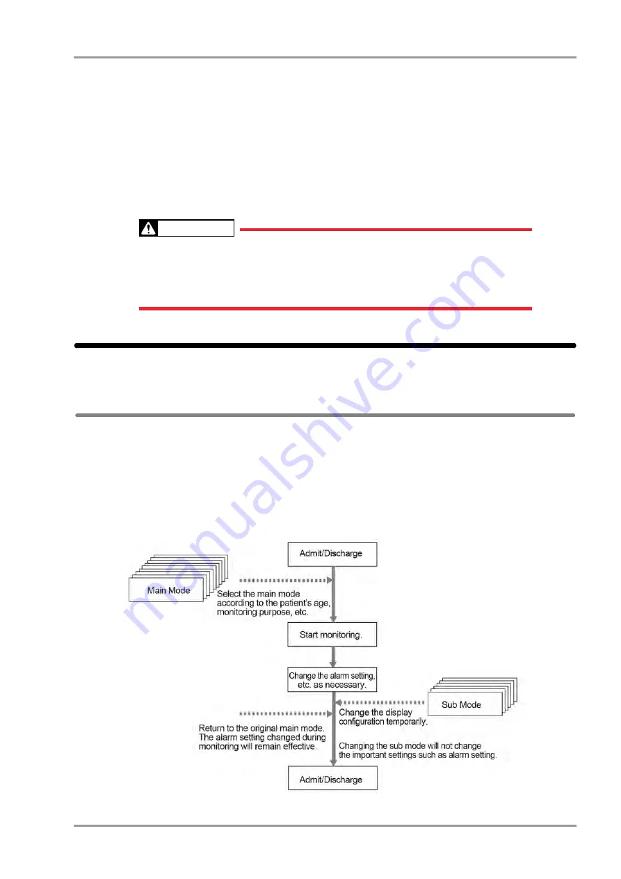
About the User Mode

For the user mode, up to 9 main modes of display configuration and alarm settings can be registered according to the 
patient's age and monitoring purpose. Also, for temporarily changing the display configuration, 6 sub modes of 
display configuration can be registered.
By programming the main mode, the alarm setups and display configuration setups at admittance of patient can be 
simplified by just selecting one of the modes. It is recommended to program the mode in rough classification such 
as patient's age, monitoring purpose (ICU or surgery), and if necessary, perform unique setup for each patient. The 
sub modes can be used when temporarily changing the display configuration such as when checking the 12-lead 
ECG, etc.

Summary of Contents for 8000 Series

Page 1: ......

Page 2: ......

Page 3: ...when Using with Other Equipment vii Pacemaker vii Non Explosion Proof vii Defibrillator vii Electrosurgical Instrument viii MRI Magnetic Resonance Imaging viii Precautions about Connections to Peripheral Devices ix Precautions for Using the Equipment ix This System ix Wired Network DS LANII DS LANIII xxi Wireless Network System xxii RTC and Data Backup xxiii Precautions about the Ventilator Monito...

Page 4: ...ction of the Super Unit 1 19 Power Connection of the Input Box 1 19 Equipotential Grounding 1 20 Chapter 2 Network System Construction Wired Network System 2 1 DS LAN Connection 2 1 DS LAN Setup 2 2 Precautions about the DS LAN 2 5 Wireless Network 2 6 Example of Wireless Network Construction 2 6 Module Attachment and Serial Communication Setup 2 7 Channel ID and Telemetry Wave Setup 2 8 Chapter 3...

Page 5: ...s Blood Gas Monitor Data Input 4 14 Connecting the Transcutaneous Blood Gas Monitor 4 14 External Device Setup 4 15 Setup for the External Device Connection 4 16 External Device Setup 4 16 Unit Module Setup 4 17 Status Output Setup 4 21 Analog Output Setup 4 22 Using the Magnetic Card Reader 4 24 Connecting the Magnetic Card Reader 4 24 Magnetic Card Reader Setup 4 24 PC Communication 4 28 Connect...

Page 6: ... I O Signal Status II Connector 6 38 Chapter 7 Replacement Parts Periodic Replacement 7 1 To Check the Periodic Replacement Period 7 1 Disposing the Equipment 7 2 Chapter 8 Cleaning Disinfecting Storing After Usage Handling the Equipment 8 1 After Using the Equipment 8 1 Display Unit 8 1 Storing the Equipment and Recording Paper 8 1 Equipment 8 1 Recording Paper 8 2 Cleaning the Equipment and Sens...

Page 7: ...heck Daily and Periodic Check 9 1 Maintenance Check 9 1 Daily Check Items and Procedures 9 2 Periodic Check Items and Procedures 9 4 Gas Measurement Accuracy Check Procedure MGU 800 MGU 810 9 8 CO2 Calibration HCP 800 HCP 810 9 10 Program Version 9 11 Software Install 9 12 ...

Page 8: ...6 Contents ...

Page 9: ...i Important Notice i For Safe Operation of the Equipment i Intended Use of this Equipment i Copyright ii Maintenance Repair Replacement ii Contact ii About This Manual iii Expression Used in This Manual iii Composition of This Manual iv ...

Page 10: ...Contents ...

Page 11: ...ng Intended Use Intended Use This equipment is intended for measuring parameters such as ECG respiration NIBP pulse rate SpO2 SpCO SpMet pulse wave temperature BP CO respiration gas concentration of CO2 N2O volatile anesthetic agent O2 spirometry BIS brain wave and monitors patient condition by displaying printing the measurement data on this equipment or central monitor and generates alarm as req...

Page 12: ...nance Repair Replacement Fukuda Denshi is liable for the safety reliability and performance of its equipment only if Maintenance modifications and repairs are carried out by authorized personnel or organization Components are used in accordance with Fukuda Denshi operating instructions A full technical description of the DS 8500 System is available from your local Fukuda Denshi sales representativ...

Page 13: ...ted by Ex Searching Alarm Suspend etc Type of Precaution Description DANGER Failure to follow this message may cause immediate threat of death or serious injury WARNING Failure to follow this message may result in death or serious injury CAUTION Failure to follow this message may cause injury or failure to the equipment NOTE Note is used to emphasize important information REFERENCE Reference is us...

Page 14: ...cs lung function alarm history other bed display full disclosure waveform 9 Printing Recorder output function 10 System Configuration Setup of the display configuration tone volume color etc 11 Troubleshooting Message list maintenance and troubleshooting of this equipment 12 Setup Item Default Value Setup details and default value 13 Accessories List of accessories and optional accessories of this...

Page 15: ...etic Resonance Imaging viii Precautions about Connections to Peripheral Devices ix Precautions for Using the Equipment ix This System ix Wired Network DS LANII DS LANIII xxi Wireless Network System xxii RTC and Data Backup xxiii Precautions about the Ventilator Monitoring xxiii Precautions about the SpO2 Sensor xxiii Precautions about the NIBP Cuff xxiv Precautions about Disposing of the Equipment...

Page 16: ...Contents ...

Page 17: ...o not damage or erase the warning labels attached to the unit These warning labels contain important descriptions for handling and operating the unit properly and safely A damaged label may compromise safe operation DS 8500 System Main Unit DSC 8500 Series Warning Labels Attached to the Unit Type of Precaution Description Indicates an imminently hazardous situation which if not avoided will result...

Page 18: ...ii Safety About the Safety Precautions Warning Label DS 8500 System Super Unit HS 8000 Series Warning Labels Attached to the Unit HS 8312 Warning Label ...

Page 19: ...that the equipment is in standby mode Electrostatic Sensitive Part Directly touching this connector part with hands should be avoided Type CF Applied Part with Defibrillation Proof Indicates the degree of protection against electric shock is Type CF Applied Part with defibrillation proof Type BF Applied Part with Defibrillation Proof Indicates the degree of protection against electric shock is Typ...

Page 20: ... power voltage Check the cable connection and polarity to ensure proper operation of the unit Make sure the power system has adequate earth ground Ensure that all cables are firmly and safely connected Pay special attention when the device is used in conjunction with other equipment as it may cause erroneous judgment and danger Precautions During Using the Equipment Always observe the equipment an...

Page 21: ...of patient ground plate ECG electrode type when using the electrosurgical knife and verify paste volume output energy when using the defibrillator Also verify that proper ground is selected Precautions about the Maintenance Never open the housing while the equipment is in operation or connected to hospital grade outlet as it may result in electric shock Precautions about Safety Check For safe oper...

Page 22: ...nnels in each zone a Coordinator However when using such telemetry in a local medical institution one person can perform both functions Select a telemetry coordinator who understands the characteristics and functionality of telemetry systems and is skilled in operating telemetry When installing telemetry the Coordinators have to understand the precautions for use of the telemetry in advance The Co...

Page 23: ...ever operate the equipment in the presence of flammable anesthetics high concentration of oxygen or inside hyperbaric chamber Also do not operate the equipment in an environment in which there is a risk of explosion Explosion or fire may result Defibrillator When defibrillating keep away from the electrodes or medicament applied to the patient chest If this is not possible remove the electrodes or...

Page 24: ...position and surgery site Place the ECG electrodes as far away as possible from the surgery site and the ground plate Do not place electrodes in the path between the surgery site and the ground plate If the electrodes are placed in this path the amount of interference will be quite large Position and electrodes as close as possible to each other Ground Plate When using electrosurgical instruments ...

Page 25: ...t including printer and hub should be located outside the Patient Environment If located inside the Patient Environment it may result in electric shock to the patient or the operator Combinations of medical equipment with non medical equipment must comply with IEC 60601 1 1 or IEC 60601 1 Never use a multiple portable socket outlet or extension cable when connecting the equipments unless it is sup...

Page 26: ...h body motion Patient with small pulse When a patient is receiving a photodynamic therapy measuring SpO2 on a same site for a long duration may cause blisters from the irradiation light of the SpO2 sensor Make sure to periodically change the sensor attachment site Before the measurement make sure the patient classification Adult Child Neonate is properly selected Otherwise correct measurement cann...

Page 27: ... not measure elevated levels of COHb or MetHb Increases in either COHb or MetHb will affect the accuracy of the SpO2 measurement For increased COHb COHb levels above normal tend to increase the level of SpO2 The level of increase is approximately equal to the amount of COHb that is present NOTE High levels of COHb may occur with a seemingly normal SpO2 When elevated levels of COHb are suspected la...

Page 28: ...e sensors Warnings about the CO2 Monitoring HCP 800 HCP 810 HPD 800 HPD 810 Only one of either HCP 800 HCP 810 HPD 800 HPD 810 can be connected When using a sampling line for intubated patients with a closed suction system do not place the airway adapter between the suction catheter and endotracheal tube This is to ensure that the airway adapter does not interfere with the functioning of the sucti...

Page 29: ...w Sensors and DRYLINE Water Traps as specified Other combinations might lead to incorrect measurements Connecting to the Respiration Circuit P7 82 Use the adult flow sensor for a patient whose tidal volume is above 150 mL Use the pediatric flow sensor for a patient whose tidal volume is below 300 mL Make sure to use the correct flow sensor depending on the patient conditions adult or pediatric and...

Page 30: ...d to the same location for a long period some patients may develop skin irritation Check the patient s skin condition periodically and change the electrode site as required For stable arrhythmia detection and ECG monitoring verify proper electrode placement lead waveform size and filter mode selection If not properly selected it may cause erroneous detection The threshold level for arrhythmia dete...

Page 31: ...with the torso placement of the limb leads Mason Likar 12 lead system may differ from that of the standard 12 lead ECG waveforms Select Used for the pacemaker setting on the patient admit discharge menu if a patient has a pacemaker The threshold values for classification of 12 lead ECG interpretation and Minnesota code are set by age and sex as follows 1 Male and Female of ages 19 years old and ab...

Page 32: ...without slippage But do not reuse on other patients to avoid cross contamination It is intended for single patient use only For details refer to the SpO2 sensor instruction manual If is displayed for the SpO2 numeric data make sure that the sensor is properly attached Measuring on a limb with NIBP cuff arterial catheter or intracatheter may result in incorrect measurement Venous congestion may cau...

Page 33: ...on recommend replacing within 96 hours If the ambient temperature of the blood pressure transducer has changed greatly the zero balance may cause the drift Perform the zero balance again An operator must not get away from a patient during the BP measurement However when getting away from the patient is necessary do not activate the Alarm Suspend and Silence functions in order not to miss any sudde...

Page 34: ... according to standard operating procedures or local regulations for the disposal of contaminated medical waste Before use carefully read the Directions for Use for the Microstream EtCO2 sampling tube Only use Microstream EtCO2 sampling lines to ensure the monitor functions properly Precautions about the CO2Monitoring HPD 800 HPD 810 Gas Unit I F The disposable airway adapter should be opened just...

Page 35: ...and if BP waveform numeric data is set to Disp OFF the PR value will not be displayed If the HR PR source is set to SpO2 and if SpO2 waveform numeric data is set to Disp OFF the PR value will not be displayed If the RR source is set to CO2 GAS and if CO2 waveform numeric data is set to Disp OFF the RR value will not be displayed If the RR source is set to CO2 GAS and if GAS waveform numeric data i...

Page 36: ... 75 mL and the flow resistance is 0 9 cmH2O at 10 L min Adjust ventilation accordingly To prevent condensation the patient breathing circuit flow sensor and pressure tubing should not be directly exposed to cooling equipment such as fans or cooling blankets Leakage of gas from the patient breathing system may occur if the pressure or gas sampling lines are not connected to the MGU 810 The pressure...

Page 37: ...a corresponded to the waveform is displayed If not the displayed waveform or numeric data may not be transmitted The default setting of bed ID is 000 If connected to a wired network with the bed ID unchanged monitoring on the central monitor will not be possible When connecting to a wired network make sure that there are no other bedside monitors with the same ID If there is more than one bedside ...

Page 38: ...CG 2 is changed on the DS 8500 System Redrawing the ST display will return the display to normal On the central monitor the respiration waveform and RR value based on the RR APNEA alarm source selected on the DS 8500 System will be displayed The monitored RR and APNEA will be the same for the central monitor and the DS 8500 System Wireless Network System When monitoring a patient using wireless te...

Page 39: ...ven though the ventilator is generating an alarm or if any other malfunction occurs immediately check the ventilator DS 8500 System cable and replace the cable if necessary If the malfunction persists stop using the equipment The alarm generation on the DS 8500 System is not guaranteed if the alarm other than specified generates at the ventilator Maintenance Manual Ventilator Measurement and Alarm...

Page 40: ...ting this equipment pack it with specified packing materials Also transport it under appropriate environment condition Operation Manual Specification P14 1 Monitoring after Power Failure When the power failure is within 30 seconds monitoring will resume with the display mode and patient information unchanged When the power failure is 30 seconds or more monitoring will resume with the default displ...

Page 41: ...ring monitoring check the electromagnetic influence and take appropriate countermeasures The following are examples of the common cause and countermeasures Cellular Phone The radio wave may cause malfunction to the device Cellular phones and radio sets should be turned off in the room building where medical device is located Lightning A lightning nearby may induce excessive voltage to the equipmen...

Page 42: ...C Electromagnetic Compatibility When using this equipment verify that it is used within the environment specified below Compliance to the Electromagnetic Emissions The DS 8500 System is intended for use in the electromagnetic environment specified below The customer or the user of the DS 8500 System should assure that it is used in such an environment Guidance and Manufacturer s Declaration Electr...

Page 43: ...l or hospital environment Surge IEC 61000 4 5 1kV differential mode 2kV common mode 1kV differential mode 2kV common mode Mains power quality should be that of a typical commercial or hospital environment Voltage dips short interruptions and voltage variations on power supply input lines IEC 61000 4 11 5 UT 95 dip in UT for 0 5 cycles 5 UT 95 dip in UT for 0 5 cycles Mains power quality should be ...

Page 44: ...trengths from fixed RF transmitters as determined by an electromagnetic site survey 1 should be less than the compliance level in each frequency range 2 Interference may occur in the vicinity of equipment marked with the following symbol Note 1 At 80MHz and 800MHz the separation distance for the higher frequency range applies Note 2 These guidelines may not apply in all situations Electromagnetic ...

Page 45: ...t Power of Transmitter W Separation Distance according to Frequency of Transmitter m 150kHz to 80MHz d 1 2 80MHz to 800MHz d 1 2 800MHz to 2 5GHz d 2 3 0 01 0 12 0 12 0 23 0 1 0 38 0 38 0 73 1 1 2 1 2 2 3 10 3 8 3 8 7 3 100 12 12 23 For transmitters rated at a maximum output power not listed above the recommended separation distance d in meters m can be determined using the equation applicable to ...

Page 46: ...xxx Safety Electromagnetic Compatibility ...

Page 47: ...ecting the AC Unit and CO2 Gas Unit 1 4 Connecting the Super Unit Input Box DS 8007 1 6 Connection of Multigas Unit 1 12 Connecting the External Monitor 1 15 Connecting the Extended Display Unit 1 16 Connecting the Mouse Optional 1 17 Power Source and Ground Connection 1 18 Power Connection of the Main Unit 1 18 Power Connection of the Super Unit 1 19 Power Connection of the Input Box 1 19 Equipot...

Page 48: ...Chapter 1 Installation of the Unit Contents ...

Page 49: ...ICU CCU surgery emergency room and ward Do not use in MRI environment or in a home care setting The power source should fulfill the following condition Use a hospital grade outlet 3 pin grounded outlet Verify power voltage and frequency before connecting to an AC power source Use the power source that can provide adequate power to the equipment Refer Operation Manual Specification P14 1 for power ...

Page 50: ...ical potential difference use the ground cable to connect each equipment s potential equalization terminal to the same ground terminal This is called equipotential grounding System Construction This section describes the connection procedure of this equipment Connect the Main Unit DSC 8500 series with necessary units such as Display Unit LC 8019T LC 8019TC LC 8015T LC 8015TC Super Unit HS 8000 ser...

Page 51: ...ing the side guide and connection guide hole NOTE Slowly attach the main unit so that it will not apply force to the connector For procedure to connect the main unit with exclusive stand refer to the OAO 44A manual 1 Main Unit DSC 8510 8530 2 DS 8500 Main Unit Stand OAO 44A option 3Fix 2 parts on the top side with accessory screws Double Washer Sems Screw M4x12 1 2 3 4 The figure shown is LC 8019T...

Page 52: ...series to the host monitor via DSA 82 is explained below WARNING The power is supplied from the host monitor When the DS 8007 is connected to the host monitor using the DSA 82 a voltage drop may occur depending on the cable connection condition which causes the charging process to temporarily cease or cease before completion 1Connect the host monitor and the DSA 82 with module connection cable CJO...

Page 53: ...ected When disconnecting the DS 8007 unlock the release lever and slide the DS 8007 along the rail in the arrow direction 3By connecting the HS 8000 HSA 80 to the DS 8007 DSA 82 using the module connection cable CJO 08SSxx the using unit can be switched The selection of which unit to use on the host monitor can be made by DS 8007 HS 8000 Switch 1 CJO 08SSxx 2 HS 8000 3 HSA 80 2 1 3 ...

Page 54: ... the different arrangement of main unit and HS 8000 DS 8007 main unit and Input Box For details of the specification and monitoring performance of the DS 8007 system refer to the operation manual of the DS 8007 system CAUTION When connecting the module connection cable press the connector tighten the screw with hand and secure it with flat blade screw driver If the connection is not secure contact...

Page 55: ... Super Unit 1Connect the main unit DSC 8500 series and HS Adapter HSA 80 using the module connection cable CJO 08SSxx 1 Main Unit DSC 8500 series 2 Module Connection Cable CJO 08SSxx 3 HS Adapter HSA 80 2Align the HS 8000 leg position with the slots on the HSA 80 1 HS 8000 2 HSA 80 1 2 3 ...

Page 56: ...ecting disconnecting the module connection cable Connection of Main Unit and Super Unit Connecting the Main Unit Super Unit and Input Box 1Connect each cable to the input box on the left side center and right side to connect the main unit HS Adapter and another input box respectively NOTE There are 3 module LAN connectors on the rear side of the Input Box Connect the module connection cable to the...

Page 57: ... to the DS 8500 system When connecting more than one input boxes change the LAN ID using the setting dial on the rear side of the input box 1Select 1 or 2 for the LAN ID which does not duplicate with other input box 2Verify that the correct ID is set by checking the LAN ID setting indicator on the front side The input box ID corresponds to the following displayed messages IB1 IB 8000 1 or IB1 IB1 ...

Page 58: ...he expansion module so that the triangle mark on the release button can be seen REFERENCE The inserted expansion module can be used by setting the parameters on the Unit Module Setup Menu Initial Settings System Unit Module By performing the setup the expansion module can be used regardless of the slot position of the Input Box 2Press the release button until it becomes flat ...

Page 59: ...he lever while the triangle mark on the release button can be seen The expansion module can be connected removed with the DS 8500 power turned ON The power should be turned OFF when connecting disconnecting the module connection cable Connecting the Main Unit and the DS 8007 1Connect the main unit DSC 8500 series and DS 8007 Adapter DSA 82 using the module connection cable CJO 08SSxx 1 Main Unit D...

Page 60: ... 8500 series 2 MGU 800 MGU 810 3 Unit Connection Cable CJO 09SSxx CAUTION When connecting the connection cable make sure to secure the connector with screws If the connection is not secure contact failure may occur Do not connect unspecified equipment to the U LINK connector on the main unit When not connecting the MGU 800 810 series make sure to select OFF for U LINK on the Menu Initial Settings ...

Page 61: ...t system in the hospital 1 Exhaust Hole 2 Exhaust Tube 3 To the gas exhaust system WARNING To protect the hospital staffs from unnecessary anesthetic agent it is strongly recommended to connect the exhaust hole to the gas exhaust system in the hospital HR 800 Recorder Unit Connection Example 1 1Connect the main unit and the HR 800 with the unit connection cable CJO 09SSxx 1 Main Unit DSC 8500 seri...

Page 62: ...00 with the unit connection cable CJO 09SSxx 1 Main Unit DSC 8500 series 2 MGU 800 MGU 810 3 HR 800 4 Unit Connection Cable CJO 09SSxx CAUTION When connecting the connection cable make sure to secure the connector with screws If the connection is not secure contact failure may occur Make sure that the power of the DS 8500 is turned OFF when connecting disconnecting the connection cable When not co...

Page 63: ...If connecting a commercially available display unit it should comply with IEC 60601 1 A commercially available monitor satisfying the following condition should be used The external monitor output resolution will be the same as the display unit When connected with Display Unit LC 8019T LC 8019TC Resolution SXGA Size 1280dot 1024dot Horizontal Frequency 63 98kHz Vertical Frequency 60 02Hz When conn...

Page 64: ...e restarted The change in type will become effective after the system is restarted If the type is not correctly set touch panel operation cannot be performed from the extended display unit If the LC 8015T LC 8015TC Display Unit is used for the main display the size of the extended display unit that can be connected is 15 inch XGA Pay attention not to accidentally connect the extended display unit ...

Page 65: ...19ET select Type 2 3Contact our service representative for the touch panel calibration NOTE The calibration must be performed after connecting the extended display unit Otherwise it will not function properly Connecting the Mouse Optional By connecting a commercially available mouse including the track ball the displayed keys can be controlled using a mouse Use the PS 2 compatible mouse 1Connect t...

Page 66: ...se a multiple portable socket outlet When using multiple ME equipment simultaneously perform equipotential grounding to prevent potential difference between the equipments Even a small potential difference may result in electric shock to the patient and the operator 1Connect the power supply cable CS 34 to the rear side of the main unit 2Connect the other end of the power supply cable CS 34 to the...

Page 67: ...ON AC power will be supplied to the Super Unit and power supply LED on the front side will light Green Power is ON and AC power is supplied Light OFF AC power is not supplied Power Connection of the Input Box When the power supply switch on the main unit is turned ON AC power will be supplied to the Input Box and LAN ID setting indicator on the front side will light ...

Page 68: ...e patient connected to these devices Pay special attention for use in Operating Room ICU CCU Cardiac Catheter Laboratory and Cardiovascular X ray room To avoid such electrical potential difference use the ground cable to connect each device s potential equalization terminal to the same ground terminal This is called equipotential grounding The ground cable is connector shape which can be connected...

Page 69: ...stem Construction Wired Network System 2 1 DS LAN Connection 2 1 DS LAN Setup 2 2 Precautions about the DS LAN 2 5 Wireless Network 2 6 Example of Wireless Network Construction 2 6 Module Attachment and Serial Communication Setup 2 7 Channel ID and Telemetry Wave Setup 2 8 ...

Page 70: ...Chapter 2 Network System Construction Contents ...

Page 71: ...nds When connecting to the DS LAN network perform DS LAN Setup under Initial Settings System DS LAN and restart the system before connecting the LAN cable Use a repeater HUB for DS LAN II network and a switching HUB for DS LAN III network The default setting of bed ID is 000 If connected to a wired network with the bed ID unchanged monitoring on the central monitor will not be possible When connec...

Page 72: ...ucted Example of Wired Network Configuration 1 Bedside Monitor DS 8500 System 2 Ethernet Branch Cable CJ 522 3 DS 7600 System Central Monitor 4 DS 5700 Central Monitor For DS LANII connection 5 HUB DS LAN Setup To connect to the central monitor using the wired network DS LAN Room Bed ID setup is necessary 1Press the Menu Initial Settings System keys The DS LAN setup screen will be displayed 2Set t...

Page 73: ...100Mbps 3Set the Room ID Bed ID CAUTION The Bed ID is factory set to 000 If connected to the wired network with the ID unchanged monitoring on the central monitor will not be possible When connected to the wired network make sure that there are no other bedside monitors with the same Bed ID If the Bed ID is duplicated monitoring on the central monitor is not possible When connecting to the DS LANI...

Page 74: ...Synchronize Hemodynamic Data with the Central Monitor 1 Press the key for Synchronize Hemodynamic Data with the Central Monitor The dropdown list will be displayed 2 Select ON or OFF ON 5 latest hemodynamic data will be synchronized between this monitor and the central monitor Other hemodynamic data will be deleted When the hemodynamic data is edited on this monitor the result will be also reflect...

Page 75: ...ayed The same parameter for the RR and apnea will be monitored on this monitor and the central monitor The alarms that can be notified to the central monitor depend on the model type and software version of the central monitor For details refer to the operation manual of the central monitor CAUTION Precautions about the DS LAN II Network The BP measurement unit should be set to mmHg The data canno...

Page 76: ...ntral monitor WARNING Some wireless combinations of telemetry transmitters may generate interference with other devices Before selecting the channel verify it will not interfere with other channels Make sure the telemetry manager of your system is aware of any changes to the telemetry channels If transmitters are used in a neighboring medical facility your facility and the neighboring facility mus...

Page 77: ...r which is corresponded to each module is required Attaching the Telemetry Transmitter Module To attach the telemetry transmitter module to the main unit DSC 8500 series optional HLX Holder is required 1Assemble the OAO 40A and telemetry transmitter module then attach them to the DSC 8500 using the accessory screws 1 Telemetry Transmitter Module 2 HLX Holder Telemetry Transmitter Module Attachment...

Page 78: ...ce the transmitting channel ID and group ID are set these will be retained even after the main power is turned OFF WARNING A password can be set to access the channel ID setup menu to allow only the telemetry channel administrator to change the channel ID Some combinations of channels may generate interference with other telemetry transmitters Before selecting a channel verify it will not interfer...

Page 79: ...try transmission 1 Press the key for Telemeter The dropdown list will be displayed 2 Select from ON OFF ON Telemetry transmission will be performed OFF Telemetry transmission will not be performed In this case channel ID will not be displayed on the home display 3Set the channel ID and group ID 1 Press the key for Channel or Group ID The New Setup window will be displayed 2 Use the numeric keypad ...

Page 80: ...Select the transmitting waveform 1 Press the key for Telemetry Wave The dropdown list will be displayed 2 Select from ECG1 ECG2 ECG1 ECG1 RESP CO2 BP1 BP2 SpO2 will be transmitted However RESP waveform will not be transmitted if APNEA source is CO2 ECG2 ECG1 ECG2 RESP CO2 BP1 SpO2 will be transmitted One of either CO2 or RESP waveform will be transmitted in accordance with the APNEA source setting...

Page 81: ...erly transmitted When transmitting the BP waveform pay attention to the displayed BP scale If the measurement unit of CO2 concentration is mmHg and 99mmHg is selected for Upper Limit of CO2 mmHg Transmission Initial Settings System Telemeter the CO2 value of 100mmHg or above will be transmitted as 99mmHg When using the NellcorTM unit the PR value of 255bpm or above will be transmitted to the centr...

Page 82: ...2 12 Chapter 2 Network System Construction Wireless Network ...

Page 83: ...3 1 Chapter 3 Using the CF card Contents Chapter 3 Using the CF card Inserting the CF card 3 1 Data Backup Copy Using the CF Card 3 1 Formatting the CF Card 3 4 Formatting the SD Card 3 5 ...

Page 84: ...Chapter 3 Using the CF card Contents ...

Page 85: ...m settings and display configuration may take large amount of time However this process can be simplified by performing the setup on one monitor and copying the data to all the other monitors using the CF card CAUTION Turn ON the power of the main unit before inserting the CF card into the CF card slot 1 CF1 The CF card slot 1 CF1 is for data backup and CF card slot 2 CF2 is for full disclosure wa...

Page 86: ...inserted in the CF card slot 2 Select the data type to read from the CF card All Data Both setup data and patient data will be read from the CF card Setup Data Setup data will be read from the CF card Patient Data Patient data will be read from the CF card 3 Press the Yes key if OK to read the data from the CF card CAUTION During access to the CF card all keys will become inoperative until the pro...

Page 87: ...aveform data Data Transfer The CF card will be formatted for data transfer 4 Press the Format key and start the format process Data that can be Backed Up Copied The setup data such as monitoring condition alarm setting and patient data such as graphic trend and tabular trend can be backed up copied By selecting All Data setup data and patient data can be both backed up copied Setup Data Data Detai...

Page 88: ...veform is explained By inserting the formatted CF card to the CF Card Slot 2 storing of the full disclosure waveform data will automatically start and the full disclosure waveform review function will become available CAUTION The full disclosure waveform card formatted on other bedside monitors and central monitors cannot be used on this equipment The full disclosure waveform card formatted on thi...

Page 89: ...inute to format the SD card Do not format the card during monitoring as all operation will not be possible during the format process During the format process do not turn OFF the power or enter into standby condition or remove the HS 8000 or SD card It may damage the SD card The SD card formatted on other HS 8000 cannot be used 1Make sure that the SD card is inserted to HS 8000 and that the card i...

Page 90: ...3 6 Chapter 3 Using the CF card Formatting the SD Card ...

Page 91: ...4 11 External Device Setup 4 11 Connecting the BISx Covidien 4 12 INVOS Data Input 4 12 Connecting to the INVOS 4 12 External Device Setup 4 13 FLOW i Data Input 4 13 Connection with the FLOW i 4 13 External Device Setup 4 14 Transcutaneous Blood Gas Monitor Data Input 4 14 Connecting the Transcutaneous Blood Gas Monitor 4 14 External Device Setup 4 15 Setup for the External Device Connection 4 16...

Page 92: ...Chapter 4 Connection to the External Devices Contents ...

Page 93: ...ware version of the ventilator Ventilator Connection Cable For Connection to DSC 8500 Status II HP 800 Servo Ventilator 900C 900D 900E CJ 400RI 70SV9 x1 Servo Ventilator 300 300A CJ 401RI 70SV3 x1 Servo Ventilator SERVO i SERVO s SERVO U SERVO n SERVO air CJ 402RI 70SVi x1 PURITAN BENNETT Ventilator 740 760 CJ 403RI 70PB x1 PURITAN BENNETT Ventilator 840 CJ 403RI 70PB x1 Drager Medical Ventilator ...

Page 94: ...arm gas supply alarm air supply alarm O2 supply alarm backup ventilation alarm respiratory rate alarm PEEP low alarm SERVO U n air airway pressure upper limit alarm expiratory minute volume upper lower limit alarm apnea alarm gas supply alarm air supply alarm O2 supply alarm overrange alarm respiratory rate alarm PEEP low alarm battery operation PB 740 PB 760 PB 840 The PB740 PB760 PB840 acquires ...

Page 95: ...When the external device is connected make sure to select the displaying parameters on the Trend Data Setup window Data Review Graphic Trend or Tabular Trend or Initial Settings External Device Main Unit HP 800 Ventilator Connection CAUTION Only one ventilator can be connected to each DS 8500 system Do not connect more than one ventilators The ventilator and anesthesia delivery system FLOW i canno...

Page 96: ...he PURITAN BENNETT ventilator the serial port RS 232C of the ventilator should be set as follows Refer to the service representative of the ventilator manufacturer Baud Rate 9600bps Data Bit 8bit Parity Bit None Stop Bit 1bit The DS 8500 system detects the ventilator alarm when the nurse call port on the ventilator outputs the alarm signal For details of ventilator setup and alarm signal output co...

Page 97: ...lator should be set as follows Refer to the service representative of the ventilator manufacturer Protocol Medibus Baud Rate 19200bps Data Bit 8bit Parity Bit Even Stop Bit 1bit 1Connect the Evita 2 dura Evita 4 Evita XL to STATUS II connector on the DS 8500 or one of STATUS II connector A or STATUS II connector B on the multiport module The illustration is example of connection of Evita 2 dura an...

Page 98: ...o RS 232C connector cable UC 232A ATEN specified by PULSION Medical Systems is required Make sure that the network for the Vigilance Vigileo is set as follows For procedure to check the Vigilance Vigileo network setting refer to the operation manual for the Vigilance Vigileo Device IFM Out Baud Rate 19200bps Parity Bit None Stop Bit 1 Data Bit 8 Flow Control 2 sec Make sure that the network for th...

Page 99: ... power of this system and the SvO2 CCO monitor is OFF SvO2 CCO Monitor Connection Connection of Vigilance 1Connect the Vigilance to the DS 8500 system The illustration is example of connection with HP 800 1 Vigilance 2 CJ 406RI 70Vigi 3 Vigilance II 4 Vigileo 5 CJ 402RI 70SVi Connection of PiCCO 1Connect the PiCCO to the DS 8500 system The illustration is example of connection with HP 800 1 CJO 19...

Page 100: ...data of CO2 concentration can be monitored on the DS 8500 System Connecting the MGU 800 MGU 810 The MGU 800 810 series Multigas Unit can be connected to the DS 8500 system via U LINK connector By connecting the Multigas Unit MGU 800 series CO2 anesthetic agent O2 N2O concentration measurement performed by the sidestream method can be monitored By connecting the MGU 810 series spirometry measuremen...

Page 101: ...he AUX connector of the HS 8000 Mainstream Method Capnostat 5 Philips Connecting the Sampling Line Covidien By connecting the FilterLine CO2 sampling line series using the CO2 Gas Unit HCP 800 HCP 810 CO2 concentration measured by intubation or non intubation can be monitored In Case of HCP 800 Connect to the AUX connector of the HS 8000 In Case of HCP 810 Connect to the AUX connector of the HS 80...

Page 102: ...recovery from anesthesia can be verified by BIS Bispectral Index value By connecting the BISx Covidien the patient s recovery from anesthesia can be verified by BIS Bispectral Index value CAUTION Refer to the BIS monitor operation manual and set the SQI value above 15 When using the BIS monitor ASCII should be set to communicate with this system Make sure that ASCII is set on the BIS monitor commu...

Page 103: ...S monitor is OFF Connecting to the Main Unit 1Use the BIS connection cable CJ0 03RS4 to connect the serial port status port on the DSC 8500 and serial port on the BIS monitor Connecting to the Multiport Module 1Use the BIS connection cable CJ 407RI 70BIS to connect the Status II connector on the HP 800 and serial port on the BIS monitor The illustration is example of connection with HP 800 1 CJ 40...

Page 104: ...data can be monitored CAUTION When connecting this system and the INVOS 5100C use only the specified connection cable Make sure that the INVOS 5100C is connected to the specified connector on this system When connecting the cable verify that the main power of this system and the INVOS 5100C are OFF Connecting to the INVOS 1Connect the INVOS 5100C to the serial connector or status connector on the ...

Page 105: ...TION The operation of anesthesia delivery system should be performed by well trained and authorized personnel When connecting the DS 8500 System and the anesthesia delivery system use only the specified connection cable Make sure that the anesthesia delivery system is connected to the specified connector on the DS 8500 System When connecting the cable make sure that the main power of this equipmen...

Page 106: ...tored The software version of the transcutaneous blood gas monitor that can be connected to the DS 8500 System is as follows TCM4 3 04 TCM5 FLEX 1 18 CAUTION When connecting the DS 8500 System and the transcutaneous blood gas monitor use only the specified connection cable Make sure that the transcutaneous blood gas monitor is connected to the specified connector on the DS 8500 System When connect...

Page 107: ...er Medical ApS 4 TCM4 In case of TCM5 FLEX 1Use the CJ 725 connection cable and the D sub 9 pin male to male gender changer to connect the TCM5 FLEX to the serial connector on the DSC 8500 1 DSC 8500 2 CJ 725 3 D sub 9 pin male to male gender changer 4 TCM5 FLEX External Device Setup To monitor the transcutaneous blood gas monitor data it is necessary to select the transcutaneous blood gas monitor...

Page 108: ...nal device is properly communicating If communication with the external device is already established through the corresponding port it is necessary to disconnect the communication in order to change the selection on this menu When connecting the VELIA ASTRAL VS ULTRA select SV 900 under Ventilator The external devices other than Vigilance BIS INVOS cannot be set to multiple ports If the setting i...

Page 109: ...r setup menu When HLX is selected perform telemetry setup channel ID etc on the Telemeter setup menu The external device parameters to be displayed on the graphic trend tabular trend needs to be selected in advance on the Trend Data Setup window Data Review Graphic Trend or Tabular Trend or Initial Settings External Device Main Unit HP 800 When TCM4 TCM5 is selected only TCM4 TCM5 FLEX can be conn...

Page 110: ...S 8007 is used Manual BP and TEMP channels can be assigned to any connectors When IB 8004 is connected to the DS 8500 system Manual will be automatically selected Operation Manual Multiparameter Connector Setup for BP TEMP CO Measurement P7 109 Example To assign BP5 to multiparameter connector 1 for the HM 800 Multi Module inserted to slot 2 of the IB 8004 1 When the HS 8000 is used When Fixed is ...

Page 111: ...e than one connectors By setting OFF for the unused connector the parameter will become selectable on another connector If the parameter assigned to the multiparameter connector and the connected relay cable does not match the connector location will be displayed in red and the connected relay cable type will be displayed SpO2 Connector Setup When using the SpO2 Module HG 810 HG 820 it is necessar...

Page 112: ...this case select 2 for SpO2 2 channels of SpO2 will be assigned to the HG 810 HG 820 CAUTION It is not possible to set only the second channel If the channel setting is duplicated one of the settings will be turned OFF Software Upgrade for Unit Module The software of the unit or module can be upgraded on the Module Install menu 1Press the Menu Maintenance Module Install keys The Module Install men...

Page 113: ... M L Level H Level H alarm will be output Level H M Level H M alarm will be output Level H M L Level H M L alarm will be output APNEA Apnea alarm will be output OFF Alarm will not be output 3 Press the key for Output Logic The dropdown list will be displayed 4 Select from Positive Logic Negative Logic Pulse Positive Logic Positive synchronized signal will be output Negative Logic Negative synchron...

Page 114: ...om Disp Lead Selected Lead 2 When Selected Lead is selected press the key for Output Lead Sel to select the output lead Select from I II III avR aVL aVF V1 V2 V3 V4 V5 V6 3Select the IBP waveform to output from the HS 8000 Select from MPA1 1 MPA1 2 MPA2 1 MPA2 2 MPA3 1 MPA3 2 4Set the synchronized signal output 1 Press the key for Signal Output and select from HR RR HR Synchronized signal based on...

Page 115: ... Lead Displayed ECG Lead Multiparameter Connector 1 1 Multiparameter Connector 1 2 Multiparameter Connector 2 1 Multiparameter Connector 2 2 Sync Signal 5When Sync Signal is selected select also the output signal 1 Press the key for Signal Output and select from HR RR HR Synchronized signal based on HR source ECG will be output RR Synchronized signal based on RR source impedance will be output 2 S...

Page 116: ...the other end of the conversion cable to the serial connector COM1 to 4 on the left side of the main unit Magnetic Card Reader Setup The initial settings for the magnetic card reader can be performed 1Press the Menu Initial Settings External Device keys The External Device setup menu will be displayed 2Select the port COM1 to 4 for the magnetic card reader 3Select Magnetic Card Reader in the Other...

Page 117: ...nd ending digit of the data read from a magnetic card NOTE The procedure to analyze the data read from the magnetic card is explained below If not analyzing the data on the magnetic card proceed to step 7 REFERENCE On the Magnetic Card Reader setup menu starting and ending digit of each data such as ID DOB Year can be set From Starting digit number of the data to be read from the magnetic card To ...

Page 118: ...t The patient ID 0123456789 is displayed at 1st to 10th digit The patient name Fukuda Denshi is displayed at 30th to 49th digit Depending on the length of patient name up to 59th digit may be used should be also included in the digit range The date of birth 19800101 is displayed at 27th to 34th digit 1 which is displayed at the 68th digit can be estimated as the character string for male It will b...

Page 119: ...nge of 1 to 255 using the left or right button 3 Press the 1 key for From or the 20 key for To REFERENCE If the data is not present on the magnetic card enter Not Used for both starting and ending digit 4 Repeat step 1 to 3 8Set the Auto Reference to Central Monitor when Reading Patient ID ON Patient information can be automatically acquired from the central monitor using the magnetic card OFF Pat...

Page 120: ... accessory cable for system connection to the serial port COM1 to 4 on the main unit External Device Setup To transmit the data to PC external device setup is required 1Press the Menu Initial Settings External Device Main Unit HP 800 keys The screen to set the connecting device type for each port will be displayed 2Select the port COM 1 to 4 to connect the PC 3Press the Other key 4Select PC Comm o...

Page 121: ... Network Printer Set the IP address MAC address and printer specification for the laser printer 1Press the Menu Initial Settings External Device Network keys The laser printer setup screen will be displayed 2Select ON OFF for Network Printer ON Laser printer will be enabled OFF Laser printer will be disabled REFERENCE Select DS LAN to output on the laser printer of DS 7700 system central monitor c...

Page 122: ...ssage will be displayed OK To register the setting press this key Cancel To cancel registering press this key 8Perform test printing Verify that the printing is properly performed CAUTION If the output characters are garbled printer specification may be incorrectly selected Refer to the operation manual of the printer and check the printer specification To Output on the DS LAN Printer Set the cent...

Page 123: ...t printing Verify that the printing is properly performed CAUTION If the output characters are garbled printer specification may be incorrectly set on the central monitor Refer to the operation manual of the printer and check the printer specification On the central monitor central monitor printer output will be prioritized over the laser printer output If the central monitor printer output is sta...

Page 124: ...4 32 Chapter 4 Connection to the External Devices Connection with the Laser Printer ...

Page 125: ...5 5 Measurement Related Setup 5 11 User Label Setup 5 11 Measurement Unit 5 12 Other Setup 5 12 User I F 5 14 Display Print Setup 5 14 Power ON Discharge 5 17 Menu Setup 5 20 Key Mask 5 21 Remote Control Setup 5 22 Operation Related Setup 5 25 Drug Calculation 5 26 System Setup 5 27 User Mode Registration 5 29 About the User Mode 5 29 To Program the User Mode 5 30 ...

Page 126: ...Chapter 5 Initial Settings Contents ...

Page 127: ...k Key mask settings for unnecessary keys Remote Control Settings for remote control Operation Settings for mouse operation window minimizing settings etc External Device Main Unit Port HP 800 Settings for external device connectors such as serial port Status II connector U Link connector Magnetic Card Reader Settings for magnetic card reader Network Network settings for laser printer Status Output...

Page 128: ...Admin Setup keys 2Enter the password The Key Lock menu will be displayed 1 The lower level items will be displayed 2 This indicates unlocked item It is displayed in white 3 This indicates locked item To change the setting an authorized password is required There are 3 levels of password which are distinguished by the color of the icon The level is in the order of red yellow green For example the f...

Page 129: ... Green Key 33333333 Before using the equipment make sure to change the password For details of the password contact Fukuda Denshi Service Representative 1Press the Menu Initial Settings Admin Setup keys 2Enter the password 3Press the Password Setup key The password setup screen will be displayed 4Enter the password REFERENCE Depending on the password the operation authorization will differ With hi...

Page 130: ...on enter the new password again REFERENCE There are 3 levels of password which are distinguished by the color of the icon The level is in the order of red yellow green and are distinguished by the entered password to display the administrator setup menu 5Set the administrator name REFERENCE Depending on the password the operation authorization will differ With higher level password the lower level...

Page 131: ... Alarm System The dropdown list will be displayed 2 Select from Fukuda Tone Melodic Tone Standard Tone Fukuda Tone The alarm tone common to DS 7000 series bedside monitor will be set Melodic Tone The alarm tone which the rhythm is the same with Standard Tone with different melody will be set Standard Tone The alarm tone complied to the IEC standard will be set 3Set the Basic Alarm Parameter 1 Pres...

Page 132: ...so if Sel Parameter is set vital alarm for unselected parameter will not generate Pay attention to not miss any significant change of the patient s vital sign as the alarms will not be generated during the Oxygenator Mode Once the cardiopulmonary bypass is finished make sure to cancel the Oxygenator Mode and return to the standard monitoring mode CAUTION If the NIBP alarm is turned OFF under the O...

Page 133: ...below 30 bpm the lower limit will be fixed to 30 bpm 40 bpm When the auto alarm is set and the lower limit is below 40 bpm the lower limit will be fixed to 40 bpm 7Set the Buzzer Tone at Speaker Failure 1 Press the key for Buzzer Tone at Speaker Failure The dropdown list will be displayed 2 Select from Enable or Disable Enable A buzzer tone will be generated instead of an alarm sound under the fol...

Page 134: ...est sound will be generated with the set volume 10Set the alarm indicator operation NOTE The alarm indicator setting is to be performed for each alarm level REFERENCE The alarm indicator flashing pattern can be set according to the alarm level The patient s condition can be checked from far distance by the difference of flashing pattern 1 Press the key for the level to set the flash pattern The pa...

Page 135: ...g to RR OFF The alarm indicator will not light NOTE If asystole alarm generates while Sync to HR is selected the green LED at the center of alarm indicator will remain lit When PR synchronized mark is displayed the LED on the alarm indicator will not flash When Sync to RR is selected and RR synchronized mark other than impedance is displayed the alarm indicator will not flash To turn OFF the alarm...

Page 136: ...hythmia Technical key The window will change according to the selected alarm group 3 Press the keys The page will switch 4 Select the alarm level from S H M L OFF for each parameter NOTE Only the displayed alarm level can be selected Press the Initialize key to initialize the alarm level setting CAUTION If OFF is set for the alarm level alarm will not be generated ...

Page 137: ... Label window will be displayed 2 Use the alphanumeric keys to enter the user label up to 3 characters The cursor position will be indicated by a red underline REFERENCE Press the display area for the user label to perform the setting The key arrangement can be selected from ABC or QWERTY The upper case lower case can be changed using the A a key CAUTION When the system is connected to DS LAN BP l...

Page 138: ...om mV mm 6 Height Weight Select the Height Weight unit from cm kg in lb 2Select the unit for each parameter NOTE When the BP CVP unit is changed the tabular graphic trend data with the previous measurement unit will be deleted Also when the unit is changed it is necessary to perform the alarm setup for the new measurement unit The measurement unit of tcpO2 tcpCO2 can be set on the TCM4 or TCM5 FLE...

Page 139: ...or from calculation Calc Calculates the mean BP from the following calculation Mean BP Systolic BP Diastolic BP x 2 3 Wave In case of NIBP maximum amplitude of oscillograph will be the mean value MAP In case of BP the following measurement will be performed 3 Sets the Arrhythmia Analysis Filter Disp Waveform The filter selected on Admit Discharge menu or ECG setup menu will be set Fixed The filter...

Page 140: ...ration is not detected inspiratory and expiratory data will become invalid and bar marks will be displayed instead Insp Only When a respiration is not detected only the inspiratory data will become valid and bar marks will be displayed for expiratory data 7 Set the Catheter Manufacturer for CC Input Press one of the keys and enter the manufacturer name on the displayed window Max 8 characters User...

Page 141: ...for the BP1 to 8 waveform 6 Select the procedure to cancel the night mode when No Change Darker Dark is set Any Key The night mode can be canceled by pressing any key on the screen Night Mode Key The night mode can be canceled by pressing the Night Mode key on the user key area or on the menu 7 The ST lead to be displayed for ST A to ST C can be set Set the lead to the key displayed in blue 8 VENT...

Page 142: ... message is present Operation Manual Numeric Data Box Display for all parameters P3 12 15 Operation Guide Display ON Operation guide message will be displayed in the window message area OFF Operation guide message will not be displayed 16 Select ON OFF for Notification when Changing Equipment Configuration ON A confirmation message will be displayed when equipment configuration is changed Connecto...

Page 143: ... will be displayed Parameters The parameter setup menu will be displayed 22 Drug Calculation Drug Calculation P5 26 23 By setting the time for Day Shift Twilight Shift Night Shift the time bar displayed at the upper part on the data waveform review screen will be displayed in different colors by each shift time Day Shift Yellow Twilight Shift Green Night Shift Blue 24 Set the key group 8 user keys...

Page 144: ...d 3 OFF At power ON and at discharge NIBP auto mode will continue even after the patient is discharged regardless of whether the next patient is admitted or not ON At power ON and at discharge NIBP auto mode will resume by starting a manual measurement for the newly admitted patient Until the NIBP auto mode is resumed or the interval is changed Standby will be displayed inside the NIBP numeric dat...

Page 145: ...ging CO2 Scale EtCO2 Peak Duration ECG1 ECG2 Size Initialize The setting will be initialized with the currently selected mode Impedance Mode ON OFF Initialize The setting will be initialized with the currently selected mode CVA Detect OFF CVA detection will be set to OFF NIBP Auto Mode OFF NIBP auto mode will be turned OFF OFF 2 5 min If NIBP Auto Mode is OFF 2 5 min interval will be set OFF 5 min...

Page 146: ...d for each group can be customized 1Press the Menu Initial Settings User I F Menu keys The menu setup screen will be displayed 2Press the group area to customize the keys The key selection for the selected group will be displayed 3Select the key position from the lower area The selected key position will be displayed in blue 4Select the key from the upper area to be assigned to the selected key po...

Page 147: ...p items are in tree structure If a upper level key is masked the lower level key will be also masked For the following tree structure if Level 3A 2 is masked only this item will be masked If Level 2A is masked the masked items will be as follows If Level 1 is masked the masked items will be as follows 1Press the Menu Initial Settings User I F Key Mask keys The key mask setup screen will be display...

Page 148: ...white frame display the lower items to perform the mask setting Even if the key mask setting is performed for the Initial Setting the Key Mask key cannot be masked 4Press for the item to display Remote Control Setup The initial settings for the remote control can be performed 1Press the Menu Initial Settings User I F Remote Control keys The Remote Control menu will be displayed 2Set the remote con...

Page 149: ...CWP input screen will be displayed NIBP Start Stop Starts stops the NIBP measurement Pressing this key will display a message on the monitor to press the Check key When the Check key is pressed the measurement will start Pressing this key during the measurement will stop the measurement Print Start Stop Starts stops the manual printing The printing duration set on the Manual Printing menu will be ...

Page 150: ...ontrol unit One remote control unit can control maximum of 100 monitors for the Room ID P and maximum of 32 monitors for Room ID A to H For procedure to set the Room Bed ID on the remote control unit refer to the operation manual of the remote control unit 1 Press the key for Room ID Bed ID The dropdown list will be displayed 2 Select from ON or OFF ON The Room ID Bed ID setup will be enabled OFF ...

Page 151: ...on can be performed 1Press the Menu Initial Settings User I F Operation keys The operation setup screen will be displayed 1 Mouse optional can be used for monitor operation ON Mouse operation will be enabled when connected OFF Mouse operation will be disabled even if connected 2 Window display can be automatically closed after fixed duration OFF Window display will not automatically close 5 to 60 ...

Page 152: ...lected from black or white 5 The pointer shape can be selected from standard large 6 Select ON OFF for Auto Hide of Pointer ON Automatically hides the pointer if the mouse is not used for 5 minutes By moving or clicking the mouse the pointer will be displayed again OFF Pointer will not be automatically hidden 7 Select the moving speed of the pointer from 5 levels Drug Calculation The following ini...

Page 153: ...S 8500 refer to the corresponding chapters in this manual Network System Construction P2 1 Connection to the External Devices P4 1 Operation Manual Data Transfer Function Using the Transport Monitor DS 8007 P4 5 1Press the Menu Initial Settings System Other keys The system setup menu will be displayed 2Set the AC filter frequency 1 Press the key for AC filter The dropdown list will be displayed 2 ...

Page 154: ...ort The data transfer function with the DS 8007 will be enabled CAUTION If the data transfer function is enabled and alarm sound suspend function is ON the alarm sound will be automatically suspended for 5 minutes when the Super Unit is connected 6Set the Data for Transfer The data to be transferred can be changed on the patient selection screen which will be displayed when connected to the Super ...

Page 155: ...ameters which requires alarm monitoring on the extended display unit central monitor make sure to display those on the display unit User Mode Registration This section explains about the user mode registration About the User Mode For the user mode up to 9 main modes of display configuration and alarm settings can be registered according to the patient s age and monitoring purpose Also for temporar...

Page 156: ...nized Mark Tone RR Alarm Apnea Source Items that can be registered for the Sub Mode The following items can be registered for the sub mode Mode Name Display Configuration To Program the User Mode This section explains how to register change the user mode 1Press the Menu Initial Settings User Mode Regist keys User mode registration screen will be displayed 2By pressing the key for each user mode th...

Page 157: ...e alarm settings of the selected alarm system will be applied 3The item to set the same settings for all modes can be selected 1 Press the Set All Modes key The screen to select the setting item will be displayed 2 Press the key for the setting item The confirmation window to apply the current setting to all modes will be displayed 3 Press OK to apply the current setting to all modes 4All user mod...

Page 158: ...5 32 Chapter 5 Initial Settings User Mode Registration ...

Page 159: ... Item Default Value Contents Chapter 6 Setup Item Default Value Setup Item 6 1 Initial Settings 6 1 External Connection Pin Assignments 6 37 RS 232C Connector Output Signal 6 37 Status I O Signal Status II Connector 6 38 ...

Page 160: ...Chapter 6 Setup Item Default Value Contents ...

Page 161: ...pend Arrhy Analysis during Noise Interference ON OFF OFF Oxygenator Mode Alarm All OFF Sel Parameter No Change All OFF Oxygenator Mode Message ON OFF ON Numeric Data BP1 to BP8 T1 to T8 Tb MODE Sub Mode OFF INDUCT SURGERY WAKING 12LEAD SUB5 SUB6 OFF Mode Extended Display 1 OFF MACHINE STAFF EXT1 3 OFF Mode Extended Display 2 OFF CIRCUL ECG CAS EXT2 3 OFF Alarm Sound Check Electrodes Enable Disable...

Page 162: ...P H M M TEMP1 to 8 H M L L Tb H M L L RR H M L M Apnea H M L H CO2In 3 H M M CO2Et 3 H M M O2In 3 H M M O2 Exp 3 H M M N2O In 3 H M M N2O Exp 3 H M M Agent In 3 H M M Agent Exp 3 H M M MAC 3 H M M SpCO1 2 H M L L SpMet1 2 H M L L SpHb1 2 H M L L PEAK 3 H M L L PEEP 3 H M L L MV 3 H M L M BIS 4 H M L M Arrhythmia Asystole S H H VF S H H VT S H H Ext Tachy S H H Ext Brady S H H Slow VT H M H Tachy S...

Page 163: ...nnection L N N Chk DS LAN Comm L N L Some parameters are not displayed due to the display layout setting L N OFF N Check Electrodes H M L L Check SpO2 Sensor Attach H M L L Super Unit Check Conn M L M IB 8000 Check Conn M L M BIS Sensor Expired N OFF N BIS Sensor Usage 24 hrs L N L BIS SQI 15 L N L BP Transducer OFF M L L 1 This setting is selectable only when Fukuda Tone is set for Alarm System 2...

Page 164: ...haracters US1 Label 2 US2 Label 3 US3 Label 4 US4 Label 5 US5 TEMP User Label Label 1 3 alphanumeric characters US1 Label 2 US2 Label 3 US3 Label 4 US4 Label 5 US5 Label 6 US6 Label 7 US7 Measurement Unit CO2 mmHg kPa mmHg BP mmHg kPa mmHg CVP mmHg kPa cmH2O mmHg kPa TEMP C F F ST mm mV mm Height Weight cm kg in lb in lb Catheter Manufacturer for CC Input Manufacturer 1 8 alphanumeric characters B...

Page 165: ...dard Right Short Trend Link with Numeric Link with Waveform Link with Numeric Display Priority HR PR VENT SpCO BP1 NIBP SpMet BP2 BP5 SpHb BP3 BP6 BIS BP4 BP7 SpO2 BP8 SpO2 CO T1 T2 T3 T4 INVOS CO2 T5 T6 SPIRO T7 T8 RR Tb HR PR BP1 BP2 BP3 BP4 SpO2 T1 T2 CO2 SPIRO RR VENT NIBP BP5 BP6 BP7 BP8 T3 T4 T5 T6 T7 T8 Tb SpCO SpMet SpHb BIS SvO2 CO INVOS Dim All Data Other than Numeric ON OFF OFF All Wind...

Page 166: ...ITROGLYCERIN 50mg NITROPRUSSIDE 50mg NOREPINEPHRIN E 4mg PHENYLEPHRINE 300mg PROCAINAMIDE 2000mg STREPTOKINASE 750000IU tPA 100mg DRUG A to G 500mg Drug Calculation Diluent Amount AMRINONE 1 to 1000 250mL AMINOPHYLLINE BRETYLIUM DOBUTAMINE DOPAMINE EPINEPHRINE HEPARIN INSULIN 100mL ISOPROTERENOL 250mL LIDOCAINE NITROGLYCERIN NITROPRUSSIDE NOREPINEPHRIN E PHENYLEPHRINE PROCAINAMIDE STREPTOKINASE tP...

Page 167: ...ctable Time 08 00 Twilight Shift 16 00 Night Shift 00 00 Key Group Setup Label A to E 8 alphanumeric characters Blank A to E Up to 8 user keys can be registered to each group Home Key Lock Menu Mode Select Alarm Silence Admit Disch Alarm Suspend Rapid Discharge NIBP Start Stop HR PR Source NIBP Cont BP Zero Print Start Stop Scale Monitor Suspend SpO2 Display ON OFF CO2 Display ON OFF Freeze GAS Di...

Page 168: ...rent Mode Mode 1 to 9 Backup Extended Display 1 Backup Mode 1 to 3 Backup Extended Display 2 Backup Mode 1 to 3 Backup Patient Classification Backup Adult Child Neonate Backup Pacemaker Backup Not Used Backup Alarm Backup Initialize Backup Display Configuration Backup Initialize Backup ECG1 ECG2 Lead Backup Initialize Backup ECG1 ECG2 Size Backup Initialize Backup Impedance Mode ON OFF Backup Init...

Page 169: ...ackup 10 sec 10 sec Power ON Discharge Item Description Default Backup Menu Item Description Default Backup Menu Setup Admit Discharge OFF Admit Discharge Admit Discharge Basic Setup OFF Tone Volume Display Config Manual Printing Auto Printing Color Brightness Night Mode Time Date Display Config Manual Printing Auto Printing Tone Volume Time Date Color Brightness Night Mode Alarm OFF Basic Circ Re...

Page 170: ...lay OFF F4 Print Start Stop F5 Night Mode F6 Tabular Trend F7 Graphic Trend F8 BP Zero Balance Room ID Bed ID Room ID A B C D E F G H P Bed ID 1 to 32 A001 OFF Select ON for Room ID Bed ID before entering the ID Operation Touch Panel etc Item Description Default Backup Mouse Setup Mouse Usage ON OFF ON Auto Hide of Pointer ON OFF ON Pointer Shape Pointer Color White Black White Moving Speed 5 leve...

Page 171: ...ive Logic Negative Logic Negative Logic Analog Output Setup DS 8007 Analog Synchronized Signal Output ON OFF ON Analog Output 1 Selected ECG Lead Displayed ECG Lead Multiparameter Connector 1 1 Multiparameter Connector 1 2 Multiparameter Connector 2 1 Multiparameter Connector 2 2 Displayed ECG Lead Analog Output 2 Multiparameter Connector 1 1 Analog Output 3 Selected ECG Lead Displayed ECG Lead Mu...

Page 172: ...0 to 2918 2921 to 2939 3000 to 3039 3100 to 3118 Telemetry Transmission Depends on the telemetry transmitter module Group ID 00 to 63 00 Transmitting Waveform ECG1 ECG1 RESP CO2 BP1 BP2 SpO2 ECG2 ECG1 ECG2 RESP CO2 BP1 SpO2 ECG1 ECG1 RESP CO2 BP1 BP2 SpO2 CO2 mmHg Upper Limit of Transmission No limit 99mmHg 99mmHg Unit Module Multiamplifier Fixed Manual Fixed 1 BP1 2 TEMP5 6 CO 2 BP5 6 TEMP1 2 CO ...

Page 173: ...ification Display Configuration Manual Printing Auto Printing Clock Setting Brightness Tone Volume Color Setup Numeric Data External Output Displayed Data All Data Displayed Data Item Description Default Backup Item Description Default Backup Main Mode 1 Site Name 8 characters ER OR ICU Mode Name 8 characters Initial Hemodynamics Cardiac Local Full Heart Neo Recovery Cardiac Sub Mode 2 Mode Name 8...

Page 174: ... Menu Alarm Silence Admit Disch BP Zero NIBP Start Stop NIBP Auto Mode NIBP Cont NIBP List Alarm Setup All Print Start Stop User Key Up Down Home Menu Alarm Silence Admit Disch BP Zero NIBP Start Stop NIBP Auto Mode NIBP Cont NIBP List Alarm Setup All Print Start Stop User Key Up Down Home User Key Down 2 2 Menu Alarm Silence Graphic Trend Group Tabular Trend Group Night Mode Key Lock Print Start ...

Page 175: ...O Bottom RR_IMP Right HR SpO2 NIBP BP1 BP2 BP3 CO2 RR_IMP SvO2 CO Bottom NIBP NIBP List Waveform ECG1 SpO2 BP Overlap 1 CO2 RESP ECG1 SpO2 BP Overlap 1 CO2 RESP User Key Numeric Data Area Below NIBP Data NIBP Start Stop NIBP Auto Mode NIBP Cont Next to RR_IMP NIBP List Next to NIBP Data NIBP Start Stop NIBP Auto Mode NIBP Cont User Key Down 1 2 Menu Alarm Silence Admit Disch BP Zero Scale Alarm Se...

Page 176: ...ght HR SpO2 NIBP BP1 CO2 RR_IMP Right HR SpO2 NIBP BP1 CO2 RR_IMP Waveform ECG12 Lead BP1 SpO2 CO2 RESP ECG12 Lead User Key Numeric Data Area Below HR 12 Lead Print Print Cancel 12L Analysis Below NIBP Data NIBP Start Stop NIBP Auto Mode NIBP Cont Below HR 12 Lead Print Print Cancel 12L Analysis Below NIBP Data NIBP Start Stop NIBP Auto Mode NIBP Cont User Key Down 1 2 Menu Alarm Silence Admit Dis...

Page 177: ...lt 19 inch Default 15 inch Backup Item Local Layout Numeric Data Bottom 2 rows Numeric Data Bottom HR SpO2 PR BP1 CO2 RR_IMP NIBP NIBP List TEMP1 2 Bottom HR SpO2 BP1 CO2 RR_IMP NIBP NIBP List TEMP1 2 Waveform ECG1 SpO2 BP1 CO2 RESP ECG1 SpO2 BP1 CO2 RESP User Key Numeric Data Area User Key Down 1 2 Menu Alarm Silence Admit Disch BP Zero NIBP Start Stop NIBP Auto Mode NIBP Cont NIBP List Alarm Set...

Page 178: ...lap 1 CO2 O2 Agent RR Overlap 2 N A RR Overlap 3 N A Block Cascade Waveform Quantity 2 Waveform ECG1 ECG2 Graphic Tabular Trend OFF Graphic Tabular Trend Size Small Main Mode Mode 4 Item Default 19 inch Default 15 inch Backup Main Mode Mode 5 Item Default 19 inch Default 15 inch Backup Item Full Layout Large Right Bottom Standard Right Bottom Numeric Data Right HR SpO2 PR NIBP BP1 BP2 BP3 GAS SvO2...

Page 179: ...Group Tabular Trend Group Night Mode Key Lock Print Start Stop User Key Up Down Home Short Trend Same as Main Mode 1 Detail Setup Numeric Data Alarm Limit Display Graph At Alarm Occurrence 3D Detail Setup Waveform Grid OFF Thickness Regular Clip OFF Fill CO2 Waveform OFF Fill O2 Waveform OFF Fill Agent Waveform OFF 12 Lead ST Wave Ref 12 Lead ST Short Trend Fill BP Overlap 1 BP1 to 4 BP Overlap 2 ...

Page 180: ...nt Start Stop User Key Up Down Home Menu Alarm Silence Graphic Trend Group Tabular Trend Group Night Mode Key Lock Print Start Stop User Key Up Down Home Short Trend Same as Main Mode 1 Detail Setup Numeric Data Alarm Limit Display Graph At Alarm Occurrence 3D Detail Setup Waveform Grid OFF Thickness Regular Clip OFF Fill CO2 Waveform OFF Fill O2 Waveform OFF Fill Agent Waveform OFF 12 Lead ST Wav...

Page 181: ...p User Key Up Down Home User Key Down 2 2 Menu Alarm Silence Graphic Trend Group Tabular Trend Group Night Mode Key Lock Print Start Stop User Key Up Down Home Menu Alarm Silence Graphic Trend Group Tabular Trend Group Night Mode Key Lock Print Start Stop User Key Up Down Home Short Trend Same as Main Mode 1 Detail Setup Numeric Data Alarm Limit Display Graph At Alarm Occurrence Reversed Detail Se...

Page 182: ...own Home Menu Alarm Silence Admit Disch BP Zero Graphic Trend Tabular Trend Recall Alarm Setup All Print Start Stop User Key Up Down Home User Key Down 2 2 Menu Alarm Silence Graphic Trend Group Tabular Trend Group Night Mode Key Lock Print Start Stop User Key Up Down Home Menu Alarm Silence Graphic Trend Group Tabular Trend Group Night Mode Key Lock Print Start Stop User Key Up Down Home Short Tr...

Page 183: ...u Alarm Silence Admit Disch BP Zero Graphic Trend Tabular Trend Recall Alarm Setup All Print Start Stop User Key Up Down Home User Key Down 2 2 Menu Alarm Silence Graphic Trend Group Tabular Trend Group Night Mode Key Lock Print Start Stop User Key Up Down Home Menu Alarm Silence Graphic Trend Group Tabular Trend Group Night Mode Key Lock Print Start Stop User Key Up Down Home Short Trend Same as ...

Page 184: ...arm Silence Admit Disch BP Zero NIBP Start Stop NIBP Auto Mode NIBP Cont Alarm Setup All Print Start Stop User Key Up Down Home User Key Down 2 2 Menu Alarm Silence Graphic Trend Group Tabular Trend Group Night Mode Key Lock Print Start Stop User Key Up Down Home Menu Alarm Silence Graphic Trend Tabular Trend Night Mode Key Lock Print Start Stop User Key Up Down Home Short Trend Display OFF Displa...

Page 185: ...ottom BIS TEMP1 2 RR_IMP Right HR SpO2 PR NIBP BP1 BP2 GAS SvO2 CO Bottom BIS TEMP1 2 Waveform ECG1 SpO2 BP1 BP Overlap 1 CO2 Agent O2 RESP ECG1 SpO2 BP1 BP2 CO2 User Key Numeric Data Area Below NIBP Data NIBP Start Stop NIBP Auto Mode NIBP Cont Next to RR_IMP NIBP List Below NIBP Data NIBP Start Stop NIBP Auto Mode NIBP Cont User Key Down 1 2 Menu Alarm Silence Admit Disch BP Zero Scale Alarm Set...

Page 186: ... Waveform OFF Fill O2 Waveform OFF Fill Agent Waveform OFF 12 Lead ST Wave Ref 12 Lead ST Short Trend Fill BP Overlap 1 BP1 to 4 BP Overlap 2 N A BP Overlap 3 N A RR Overlap 1 CO2 O2 Agent RR Overlap 2 N A RR Overlap 3 N A Block Cascade Waveform Quantity 2 Waveform ECG1 ECG2 Graphic Tabular Trend OFF Graphic Tabular Trend Size Small Sub Mode Mode 2 Item Default 19 inch Default 15 inch Backup ...

Page 187: ...t Start Stop User Key Up Down Home User Key Down 2 2 Menu Alarm Silence Trend Group Tabular Trend Group Night Mode Key Lock Print Start Stop User Key Up Down Home Menu Alarm Silence Trend Group Tabular Trend Group Night Mode Key Lock Print Start Stop User Key Up Down Home Short Trend Same as Sub Mode Mode 1 Detail Setup Numeric Data Alarm Limit Display Graph At Alarm Occurrence 3D Detail Setup Wav...

Page 188: ...d Group Tabular Trend Group Night Mode Key Lock Print Start Stop User Key Up Down Home Menu Alarm Silence Graphic Trend Group Tabular Trend Group Night Mode Key Lock Print Start Stop User Key Up Down Home Short Trend Same as Sub Mode 1 Detail Setup Numeric Data Alarm Limit Display Graph At Alarm Occurrence 3D Detail Setup Waveform Grid OFF Thickness Regular Clip OFF Fill CO2 Waveform OFF Fill O2 W...

Page 189: ...arm Silence Graphic Trend Tabular Trend Night Mode Key Lock Print Start Stop User Key Up Down Home Short Trend Same as Sub Mode 1 Detail Setup Numeric Data Alarm Limit Display Graph At Alarm Occurrence 3D Detail Setup Waveform Grid OFF Thickness Regular Clip OFF Fill CO2 Waveform OFF Fill O2 Waveform OFF Fill Agent Waveform OFF 12 Lead ST Wave Ref 12 Lead ST Short Trend Fill BP Overlap 1 BP1 to 4 ...

Page 190: ...op User Key Up Down Home Short Trend Same as Sub Mode 1 Detail Setup Numeric Data Alarm Limit Display Graph At Alarm Occurrence 3D Detail Setup Waveform Grid OFF Thickness Regular Clip OFF Fill CO2 Waveform OFF Fill O2 Waveform OFF Fill Agent Waveform OFF 12 Lead ST Wave Ref 12 Lead ST Short Trend Fill BP Overlap 1 BP1 to 4 BP Overlap 2 N A BP Overlap 3 N A RR Overlap 1 CO2 O2 Agent RR Overlap 2 N...

Page 191: ...splay Graph At Alarm Occurrence 3D Detail Setup Waveform Grid ON Thickness Regular Clip OFF Fill CO2 Waveform OFF Fill O2 Waveform OFF Fill Agent Waveform OFF 12 Lead ST Wave Ref 12 Lead ST Short Trend Fill BP Overlap 1 BP1 to 4 BP Overlap 2 N A BP Overlap 3 N A RR Overlap 1 CO2 O2 Agent RR Overlap 2 N A RR Overlap 3 N A Block Cascade Waveform Quantity 2 Waveform ECG1 ECG2 Extended Display 1 Mode ...

Page 192: ...m Occurrence 3D Detail Setup Waveform Grid ON Thickness Regular Clip OFF Fill CO2 Waveform OFF Fill O2 Waveform OFF Fill Agent Waveform OFF 12 Lead ST Wave Ref 12 Lead ST Short Trend Fill BP Overlap 1 BP1 to 4 BP Overlap 2 N A BP Overlap 3 N A RR Overlap 1 CO2 O2 Agent RR Overlap 2 N A RR Overlap 3 N A Block Cascade Waveform Quantity 2 Waveform ECG1 ECG2 Extended Display 1 Mode 2 Item Default 19 i...

Page 193: ...O2 Waveform OFF Fill Agent Waveform OFF 12 Lead ST Wave Ref 12 Lead ST Short Trend Fill BP Overlap 1 BP1 to 4 BP Overlap 2 N A BP Overlap 3 N A RR Overlap 1 CO2 O2 Agent RR Overlap 2 N A RR Overlap 3 N A Block Cascade Waveform Quantity 2 Waveform ECG1 ECG2 Extended Display 1 Mode 3 Item Default 19 inch Default 15 inch Backup Extended Display 2 Mode 1 Item Default 19 inch Default 15 inch Backup Ite...

Page 194: ... A RR Overlap 1 CO2 O2 Agent RR Overlap 2 N A RR Overlap 3 N A Block Cascade Waveform Quantity 2 Waveform ECG1 ECG2 Extended Display 2 Mode 1 Item Default 19 inch Default 15 inch Backup Extended Display 2 Mode 2 Item Default 19 inch Default 15 inch Backup Item Circ Layout Standard Right Numeric Data Right HR ST VPC SpO2 NIBP BP1 TEMP1 2 RR_IMP Right HR ST VPC SpO2 NIBP BP1 TEMP1 2 RR_IMP Waveform ...

Page 195: ...2 Waveform ECG1 ECG2 Extended Display 2 Mode 2 Item Default 19 inch Default 15 inch Backup Extended Display 2 Mode 3 Item Default 19 inch Default 15 inch Backup Item Extended 2 Mode 3 Layout Numeric Data Bottom 2 rows Numeric Data Bottom HR SpO2 RR_IMP BP1 NIBP CO2 Bottom HR SpO2 NIBP BP1 CO2 RR_IMP Waveform ECG1 SpO2 BP1 CO2 RESP ECG1 SpO2 BP1 CO2 RESP User Key Numeric Data Area User Key Down 1 2...

Page 196: ...verlap 1 CO2 O2 Agent RR Overlap 2 N A RR Overlap 3 N A Block Cascade Waveform Quantity 2 Waveform ECG1 ECG2 Extended Display 2 Mode 3 Item Default 19 inch Default 15 inch Backup Item Description Default Backup Key Lock OFF red key yellow key green key for each item Red key for the following items Initial Settings System Telemeter Maintenance Other settings OFF Password Setup Administrator name 8 ...

Page 197: ...7 NC Not connected 8 NC Not connected No Signal Type Note Signal Level 1 RESET Reset 2 NC Not connected 3 TxD Serial Transmission Data Output RS232C 4 GND_ISO Isolation Ground 5 RxD Serial Reception Data Input RS232C 6 5V 5V Power Supply Input 5V power supply 150mA 7 NC Not connected 8 NC Not connected No Signal Type Note Signal Level 1 RESET Reset 2 DIG_L Digital Output LOAD TTL Extended Function...

Page 198: ...C Not connected No Signal Type Note Signal Level 1 COM_RST Reset Output Open Collector Output 2 NC Not connected 3 TxD Serial Transmit Data Output RS232C 4 GND GND 5 RxD Serial Reception Data Input RS232C 6 5V 5V Power 5V power supply 150mA 7 NC Not connected 8 NC Not connected No Signal Type Note Signal Level 1 ALARM_OUT1 Alarm Output1 Logic TTL 2 ALARM_OUT2 Alarm Output2 Isolation Photo MOS Rela...

Page 199: ...7 1 Chapter 7 Replacement Parts Contents Chapter 7 Replacement Parts Periodic Replacement 7 1 To Check the Periodic Replacement Period 7 1 Disposing the Equipment 7 2 ...

Page 200: ...Chapter 7 Replacement Parts Contents ...

Page 201: ...acement Period The usage hours for the part which requires periodic replacement can be displayed It can be used as an indication of replacement period for each part 1Press the Menu Maintenance Usage Time keys The Usage Time window will be displayed Periodic Replacement Parts Periodic Replacement Period DSC 8500 Series Main Unit Short Term Backup Battery 3 years The usable life of the short term ba...

Page 202: ...rn the rotary switch to original position For details please refer to our service representative Disposing the Equipment CAUTION When disposing of the equipment accessories follow the regulations of local authority or each institution Do not dispose of as ordinary waste When disposing of the battery separate it from other wastes and contact your nearest service representative If there is risk of i...

Page 203: ...isplay Unit 8 1 Storing the Equipment and Recording Paper 8 1 Equipment 8 1 Recording Paper 8 2 Cleaning the Equipment and Sensors 8 2 Touch Panel 8 2 Housing 8 3 Fan Filter 8 4 NIBP Cuff and Air Hose 8 4 BP Transducer 8 4 SpO2 Sensor 8 4 Temperature Probe 8 5 Cardiac Output Relay Cable 8 5 Airway Adapter for Capnostat 5 8 5 Water Trap Multigas Unit 8 5 BISx 8 7 ...

Page 204: ...Chapter 8 Cleaning Disinfecting Storing Contents ...

Page 205: ... will not affect monitoring operation Due to its material characteristic the touch panel expands contracts depending on the temperature humidity When the touch panel is left unused for a while or when the ambient temperature is low the surface film of the touch panel may expand but this is not an abnormal condition This expansion will be reduced in few hours or half a day after the power is turned...

Page 206: ...nce the display unit of the DS 8500 System incorporates a touch panel finger prints and other stains are likely to appear on the touch panel Follow the procedure below to clean the touch panel For disinfecting procedure refer to the next section Housing CAUTION Never use strong acidic cleaning solution To clean the touch panel use an optional cleaning cloth eyeglass cleaning cloth soft cotton clot...

Page 207: ...ing do not allow chemical solution to enter the equipment or connectors Do not use organic solvents thinner toluene or benzene to avoid damaging the resin case Do not polish the equipment with abrasive chemical cleaner alkaline or acidic detergent Otherwise the surface resin or paint coating may be damaged resulting in discoloration scratches and other problems For the precautions for storing and ...

Page 208: ...on the bladder and cuff shell match Make sure that the cuff hose is threaded through one of the hose openings in the cuff BP Transducer Disinfect the blood pressure transducers according to the manufacturer s guidelines Do not reuse re sterilize the disposable type transducers SpO2 Sensor Disinfect the SpO2 sensor according to the manufacturer s guidelines Do not reuse resterilize the disposable S...

Page 209: ...propyl alcohol cotton 2Dry it completely with air before reusing Cardiac Output Relay Cable Do not reuse resterilize the cardiac output catheter When cleaning follow the procedure below 1Wipe the cable using 70 isopropyl alcohol cotton 2Dry it completely with air before reusing Airway Adapter for Capnostat 5 Sterilize the airway adapter according to the manufacturer s guidelines Do not reuse re st...

Page 210: ... mL min 1Remove the water trap by pressing and holding the release button on the holder part 2Unscrew the reservoir from the filter to separate them 3Empty the reservoir WARNING The contents of the water trap should be handled as a potential infection hazard 4Screw back the reservoir and reattach the water trap ...

Page 211: ... water to aid in cleaning After cleaning wipe the PIC connector ends with alcohol and allow to dry completely Residual moisture inside the connector may affect BISx performance Use lint free absorbent towels dampened with a 10 bleach solution or a commercial disinfectant CAUTION BIS sensor is disposable Do not reuse it Do not reuse the BIS sensor to other patients It may cause cross infection The ...

Page 212: ...8 8 Chapter 8 Cleaning Disinfecting Storing Cleaning the Equipment and Sensors ...

Page 213: ... Daily and Periodic Check 9 1 Maintenance Check 9 1 Daily Check Items and Procedures 9 2 Periodic Check Items and Procedures 9 4 Gas Measurement Accuracy Check Procedure MGU 800 MGU 810 9 8 CO2 Calibration HCP 800 HCP 810 9 10 Program Version 9 11 Software Install 9 12 ...

Page 214: ...Chapter 9 Maintenance Check Contents ...

Page 215: ...ents arising from lack of maintenance Contact your nearest service representative for information on basic performance For additional information required by the service and technical engineers to service the equipment refer to your nearest service representative CAUTION Do not open the housing Do not allow alcohol or other liquids to enter the equipment Daily Check Perform the daily check accordi...

Page 216: ...the lower left of the display unit should light The date and time should be correct 02 Function Turn ON the power of the main unit and check whether it operates normally The power supply LED of the main unit should light 03 Function When IB 8004 is used The set LAN ID indicator should light 04 Function When HS 8000 HSA 80 is used The home display should appear and the power LED of the HS 8000 shou...

Page 217: ...vious calibration Refer to the following caution Should be within one year Check the remaining time until the next calibration Menu CO2 CO2 Cal Should not be 0 hrs 15 Sampling Tube When MGU 800 MGU 810 is used Check that it is not reused Extra supplies should be kept 16 Airway Adapter When MGU 800 MGU 810 is used Check that it is not reused Extra supplies should be kept 17 Flow Sensor WhenMGU 810i...

Page 218: ...he exterior 02 Cables Check that neither damage nor broken wire is found in all cables Neither damaged nor broken wire should be found 03 Printing Paper Visually check the installed condition The paper should be correctly installed 04 Operation Manual Check that accompanying documents operational manual etc are stored in specified location Should be stored in specified location No Check Items Chec...

Page 219: ...layed The Lead OFF message for the removed electrode should be displayed No Check Items Check Procedure Criteria 5 Respiration Impedance Measurement 01 Respiration Rate display accuracy Input the respiration signal of 20 Bpm with the following setting from the simulator and check the displayed RR value on the monitor Baseline Impedance 1500Ω Detection Lead II LL Respiration Waveform Normal Amplitu...

Page 220: ...teria 11 CO2 Concentration Optional 01 CO2 Concentration Calibration HCP 800 HCP 810 Perform calibration according to the procedure explained in Chapter 9 Maintenance Check Maintenance Manual The calibration should complete without error 02 CO2 Concentration Measurement Perform measurement with 5 calibration gas and check the displayed CO2 concentration value on the monitor The displayed CO2 conce...

Page 221: ...xiliary current SFC under single failure condition using a leak measurement safety tester Test according to the test method of IEC 60601 1 It should be 0 05 mA or less No Check Items Check Procedure Criteria 14 Electrical Safety Perform the following check item as appropriate Check these items when you have disassembled the equipment to check or replace the boards or unit 08 Protective ground resi...

Page 222: ...ent check will be displayed on the Gas Accuracy Check screen During the accuracy check gas measurement and other gas function cannot be used To correct the gas measurement drift zero calibration is necessary The automatic zeroing is performed periodically but perform it manually as necessary Zeroing should be performed with the transducers opened to air During accuracy check the pressure display o...

Page 223: ...from start up of the gas unit When the warming up process completes Supply calibration gas message will be displayed 3Connect the calibration gas cylinder to multigas unit 4Supply the calibration gas and wait for 30 seconds until the gas measurement value becomes stable 5Check the measurement accuracy of each gas The measurement accuracy criteria of each gas are as follows CO2 5 0 1 1 O2 45 0 5 7 ...

Page 224: ...t date If any of the following messages is displayed start the procedure again from step 2 CAL error CAL GAS error Auto Zero fail No stable gas flow CAL failure 6Press the Cal Complete key to end the calibration CAUTION Perform the calibration 5 minutes after turning ON the power on the HCP 800 HCP 810 Do not disconnect the sampling tube during calibration If disconnected calibration will cease Co...

Page 225: ...sion screen software version of the main unit and modules can be verified 1Press the Menu Maintenance keys The software version screen will be displayed The software version boot version date comment required for the DS 8500 system will be displayed DSC 8500 Main Unit Software Display Unit LC 8019T LC 8019TC LC 8015T LC 8015TC HS 8000 DS 8007 Software HR 800 Recorder Unit Software MGU 800 810 Mult...

Page 226: ...tall Software Install The software can be updated on the install screen 1Press the Menu Maintenance Install keys The software install screen will be displayed NOTE Users cannot perform the software update process Contact our service representative ...

Page 227: ...ter 5 13 Arrhythmia Analysis Filter 5 1 5 13 6 4 Fan Filter 8 4 FLOW i 4 14 G Gas Accuracy Check 9 8 H HS Adapter HSA 80 1 7 L Laser Printer Connection 4 29 M Module Connection Cable CJO 08SSxx 1 7 1 11 N Negative Logic 4 23 O Out of Measurement Range 2 6 Output Logic 4 23 P Periodic Check 9 1 Periodic Inspection 9 1 PiCCO 4 7 Positive Logic 4 23 PulsioFlex 4 8 S Selected ECG Lead 4 23 SERVO i s 4...

Page 228: ...Index 2 Index ...

Page 229: ......

Page 230: ......

Reviews: