A
B
A
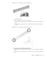
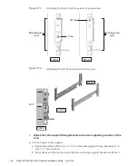
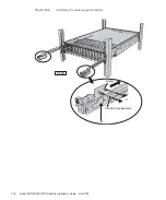
Figure
3-68
Removing
pins
from
the
Type-1
rail
-
For
the
Type-2
rail
Remove
the
pins
at
the
front
and
rear
of
the
rail.
a.
Remove
the
pins
(A
in
at
the
front
and
rear
of
the
left
and
right
rails.
b.
Store
the
removed
pins
(four
pins
in
total)
for
future
use
when
the
chassis
is
moved.
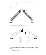
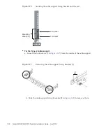
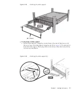
Figure
3-69
Removing
pins
from
the
Type-2
rail
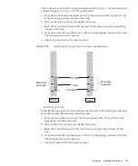
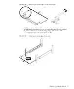
4.
Remove
each
screw
from
the
side
of
the
rail.
For
the
Type-1
rail,
remove
the
one
screw
(A
in
from
the
side
of
the
rail.
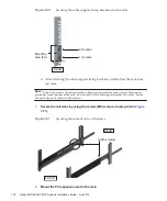
For
the
Type-2
rail,
loosen
the
two
screws
(B
in
from
the
side
of
the
rail.
Chapter
3
Installing
the
System
125
Summary of Contents for M10 Series
Page 1: ...Fujitsu M10 SPARC M10 Systems Installation Guide Manual Code C120 E678 12EN July 2015 ...
Page 10: ...Fujitsu M10 SPARC M10 Systems Installation Guide July 2015 x ...
Page 156: ...Fujitsu M10 SPARC M10 Systems Installation Guide July 2015 142 ...
Page 176: ...Fujitsu M10 SPARC M10 Systems Installation Guide July 2015 162 ...
Page 208: ...Fujitsu M10 SPARC M10 Systems Installation Guide July 2015 194 ...
Page 240: ...Fujitsu M10 SPARC M10 Systems Installation Guide July 2015 226 ...
Page 252: ...Fujitsu M10 SPARC M10 Systems Installation Guide July 2015 238 ...
Page 290: ...Fujitsu M10 SPARC M10 Systems Installation Guide July 2015 276 ...
Page 310: ...Fujitsu M10 SPARC M10 Systems Installation Guide July 2015 296 ...
Page 336: ...Fujitsu M10 SPARC M10 Systems Installation Guide July 2015 322 ...
Page 368: ...Fujitsu M10 SPARC M10 Systems Installation Guide July 2015 354 ...
Page 374: ...Fujitsu M10 SPARC M10 Systems Installation Guide July 2015 360 ...


