Supermicro SCLA26, User Manual
The Supermicro SCLA26 User Manual is your essential guide to unlocking the full potential of this high-performance product. Easily download your free manual from manualshive.com to access detailed instructions, troubleshooting tips, and valuable insights, ensuring a seamless and optimized user experience.
Share
Download


Reviews:
No comments
Related manuals for SCLA26

Ethernet Routing Switch 8010
Brand: Nortel Pages: 16

A-F5000
Brand: HP Pages: 97

A-F5000
Brand: HP Pages: 145

LC1.15E
Brand: Philips Pages: 24

L04E AD
Brand: Philips Pages: 28

L01H.1A
Brand: Philips Pages: 74

L04LAA
Brand: Philips Pages: 94

L9.1A
Brand: Philips Pages: 113

L9.2E AA
Brand: Philips Pages: 122

IX2000
Brand: Viglen Pages: 58

NGC-105
Brand: Barco Pages: 39

SC828 Series
Brand: Supermicro Pages: 56

EN-898X
Brand: Enlight Pages: 45

FRM220-CH08
Brand: CTC Union Pages: 20
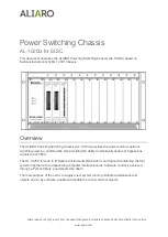
AL-1020U
Brand: ALIARO Pages: 16


