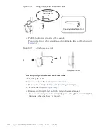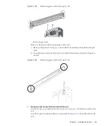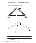
C
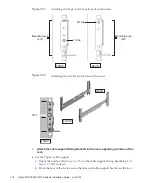
REAR
(M3 screws)
REAR
D
Circular hole
sections
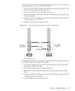
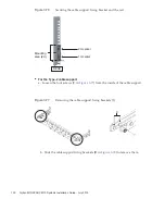
Figure
3-55
Attaching
the
cable
support
●
For
the
Type-2
cable
support
a.
Tilt
the
cable
support
to
align
the
circular
holes
at
the
rear
of
the
groove
with
the
two
screws
of
a
cable
support
fixing
bracket
(D
in
and
attach
it.
Level
the
cable
support.
Then,
align
the
circular
holes
at
the
other
side
with
the
two
screws,
and
attach
it.
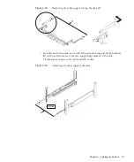
Figure
3-56
Attaching
the
cable
support
(1)
Fujitsu
M10/SPARC
M10
Systems
Installation
Guide
・
July
2015
116
Summary of Contents for M10 Series
Page 1: ...Fujitsu M10 SPARC M10 Systems Installation Guide Manual Code C120 E678 12EN July 2015 ...
Page 10: ...Fujitsu M10 SPARC M10 Systems Installation Guide July 2015 x ...
Page 156: ...Fujitsu M10 SPARC M10 Systems Installation Guide July 2015 142 ...
Page 176: ...Fujitsu M10 SPARC M10 Systems Installation Guide July 2015 162 ...
Page 208: ...Fujitsu M10 SPARC M10 Systems Installation Guide July 2015 194 ...
Page 240: ...Fujitsu M10 SPARC M10 Systems Installation Guide July 2015 226 ...
Page 252: ...Fujitsu M10 SPARC M10 Systems Installation Guide July 2015 238 ...
Page 290: ...Fujitsu M10 SPARC M10 Systems Installation Guide July 2015 276 ...
Page 310: ...Fujitsu M10 SPARC M10 Systems Installation Guide July 2015 296 ...
Page 336: ...Fujitsu M10 SPARC M10 Systems Installation Guide July 2015 322 ...
Page 368: ...Fujitsu M10 SPARC M10 Systems Installation Guide July 2015 354 ...
Page 374: ...Fujitsu M10 SPARC M10 Systems Installation Guide July 2015 360 ...


