


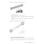

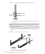


Note
-
After
removing
or
loosening
the
screw
or
screws,
hold
the
rail
level
with
both
hands.
If
the
rail
tilts,
it
may
stretch.
A
A
B
FRONT
FRONT
FRONT
FRONT
C
FRONT
FRONT
FRONT
FRONT
B
B
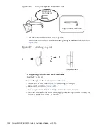
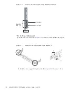
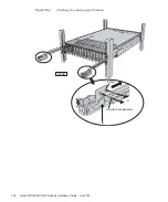
Note
-
After
removing
its
screw,
hold
the
rail
level
with
both
hands.
If
the
rail
tilts,
it
may
stretch.
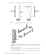
Figure
3-70
Screw
on
the
side
of
the
Type-1
rail
Figure
3-71
Screws
on
the
side
of
the
Type-2
rail
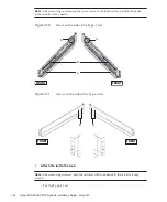
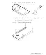
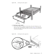
5.
Attach
the
rail
to
the
rack.
-
For
the
Type-1
rail
Fujitsu
M10/SPARC
M10
Systems
Installation
Guide
・
July
2015
126
Summary of Contents for M10 Series
Page 1: ...Fujitsu M10 SPARC M10 Systems Installation Guide Manual Code C120 E678 12EN July 2015 ...
Page 10: ...Fujitsu M10 SPARC M10 Systems Installation Guide July 2015 x ...
Page 156: ...Fujitsu M10 SPARC M10 Systems Installation Guide July 2015 142 ...
Page 176: ...Fujitsu M10 SPARC M10 Systems Installation Guide July 2015 162 ...
Page 208: ...Fujitsu M10 SPARC M10 Systems Installation Guide July 2015 194 ...
Page 240: ...Fujitsu M10 SPARC M10 Systems Installation Guide July 2015 226 ...
Page 252: ...Fujitsu M10 SPARC M10 Systems Installation Guide July 2015 238 ...
Page 290: ...Fujitsu M10 SPARC M10 Systems Installation Guide July 2015 276 ...
Page 310: ...Fujitsu M10 SPARC M10 Systems Installation Guide July 2015 296 ...
Page 336: ...Fujitsu M10 SPARC M10 Systems Installation Guide July 2015 322 ...
Page 368: ...Fujitsu M10 SPARC M10 Systems Installation Guide July 2015 354 ...
Page 374: ...Fujitsu M10 SPARC M10 Systems Installation Guide July 2015 360 ...