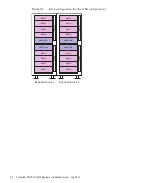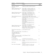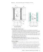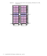
BB#03
BB#02
BB#01
BB#00
1U
Note
-
For
the
SPARC
M10-4
and
M10-4S,
the
cable
support
at
the
chassis
rear
moves
underneath
the
chassis
during
maintenance,
so
do
not
mount
the
chassis
on
the
lowest
shelf
(1U)
of
the
rack.
Note
-
The
dimensions
shown
in
the
conditions
do
not
include
any
protrusions.
Standalone
configuration
(SPARC
M10-1
or
SPARC
M10-4)/building
block
configuration
(direct
connection
between
each
SPARC
M10-4S
chassis)
Each
chassis
of
the
SPARC
M10
systems
is
designed
for
mounting
in
an
equipment
rack.
If
the
SPARC
M10-4S
units
are
connected
by
cables,
mount
the
units
side
by
side
in
a
rack
with
no
gap
between
them.
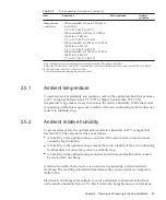
Figure
2-3
Chassis
mounting
locations
(corresponding
to
BB-IDs)
for
the
4BB
configuration
For
mounting
in
a
third-party
rack,
it
is
the
customer's
responsibility
to
confirm
that
the
rack
specifications
match
the
specifications
and
requirements
for
the
SPARC
M10
systems
(see
and
).
Fujitsu
M10/SPARC
M10
Systems
Installation
Guide
・
July
2015
24
Summary of Contents for M10 Series
Page 1: ...Fujitsu M10 SPARC M10 Systems Installation Guide Manual Code C120 E678 12EN July 2015 ...
Page 10: ...Fujitsu M10 SPARC M10 Systems Installation Guide July 2015 x ...
Page 156: ...Fujitsu M10 SPARC M10 Systems Installation Guide July 2015 142 ...
Page 176: ...Fujitsu M10 SPARC M10 Systems Installation Guide July 2015 162 ...
Page 208: ...Fujitsu M10 SPARC M10 Systems Installation Guide July 2015 194 ...
Page 240: ...Fujitsu M10 SPARC M10 Systems Installation Guide July 2015 226 ...
Page 252: ...Fujitsu M10 SPARC M10 Systems Installation Guide July 2015 238 ...
Page 290: ...Fujitsu M10 SPARC M10 Systems Installation Guide July 2015 276 ...
Page 310: ...Fujitsu M10 SPARC M10 Systems Installation Guide July 2015 296 ...
Page 336: ...Fujitsu M10 SPARC M10 Systems Installation Guide July 2015 322 ...
Page 368: ...Fujitsu M10 SPARC M10 Systems Installation Guide July 2015 354 ...
Page 374: ...Fujitsu M10 SPARC M10 Systems Installation Guide July 2015 360 ...


