background image

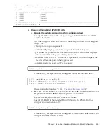
XSCF>


showcod


-p


0

PROC


Permits


assigned


for


PPAR


0:


64

XSCF>


setcod


-p


0


-s


cpu


128

XSCF>


showcod


-p


0

PROC


Permits


assigned


for


PPAR


0:


128

XSCF>


console


-p


0

#


ldm


list-domain

NAME


STATE


FLAGS


CONS


VCPU


MEMORY


UTIL


UPTIME

primary


active


-n-cv-


UART


32


28G


0.0%


2h


3m

guest0


active


-n----


5100


64


64G


3.1%


33m

root-dom0


active


-n--v-


5000


32


32G


3.1%


47m

Note


-


Suppose


you


install


the


installed


SPARC


M10-4S


together


with


a


PCI


expansion


unit

c.


If


the


assigned


resources


are


insufficient,


execute


the


setcod


command


to


assign


CPU


resources


to


the


physical


partition.


The


following


example


assigns


128


CPU


core


resources


to


the


physical


partition.

d.


If


you


have


assigned


CPU


resources,


execute


the


showcod


command


again


to


check


the


information


on


the


CPU


resources


assigned


to


the


physical


partition.

11.

Check


the


operation


status


of


logical


domains.

a.


Connect


to


the


control


domain


console


of


the


physical


partition,


and


then


log


in.

b.


Execute


the


ldm


list-domain


command


to


check


the


operation


status


of


the


logical


domains.


Check


the


operation


status


of


the


logical


domains


through


the


combination


of


[STATE]


and


[FLAGS].


When


[STATE]


is


"active,"


the


second


character


from


the


left


of


the


string


in


[FLAGS]


has


one


of


the


following


meanings:


"n":


Oracle


Solaris


operating


"t":


OpenBoot


PROM


state


"-":


Another


state


(including


cases


in


which


STATE


is


not


active)


In


the


following


example,


you


can


see


that


the


control


domain,


one


guest


domain,


and


one


root


domain


are


operating.

12.

Incorporate


the


system


board


of


the


installed


SPARC


M10-4S


into


the


physical


partition.

Fujitsu


M10/SPARC


M10


Systems


Installation


Guide


July


2015

258

Summary of Contents for M10 Series

Page 1: ...Fujitsu M10 SPARC M10 Systems Installation Guide Manual Code C120 E678 12EN July 2015 ...

Page 2: ... et technologies décrits dans ce document De même ces produits technologies et ce document sont protégés par des lois sur le droit d auteur des brevets et d autres lois sur la propriété intellectuelle et des traités internationaux Ce document le produit et les technologies afférents sont exclusivement distribués avec des licences qui en restreignent l utilisation la copie la distribution et la déc...

Page 3: ...ote on configurations with the PCI expansion unit connected 13 Chapter 2 Planning and Preparing for System Installation 17 2 1 Safety Precautions 17 2 2 Items Requiring Confirmation before Installation 21 2 3 Confirming the Physical Specifications of the System 22 2 3 1 Size and weight 23 2 4 Confirming Rack Specifications 23 2 4 1 Mounting conditions for general racks 23 2 4 2 Installation area f...

Page 4: ...er Supply Facilities 54 2 9 1 Electrical specifications 54 2 9 2 Power cord specifications 59 2 9 3 Breaker characteristics 60 2 9 4 Grounding requirements 61 2 10 Checking External Interface Port Specifications 62 2 10 1 Network configuration example 65 Chapter 3 Installing the System 67 3 1 Preparing the Necessary Tools Information for Installation 67 3 2 Confirming Delivered Components 68 3 2 1...

Page 5: ... Block Connections 143 4 1 Setting the ID BB ID Identifying a Chassis 143 4 2 Connecting Cables for Direct Connections between Chassis 145 4 2 1 Connecting crossbar cables 145 4 2 2 Connecting XSCF cables 147 4 3 Connecting Cables for Connections through Crossbar Boxes 148 4 3 1 Changing crossbar cables when subsequently installing expansion rack 2 148 4 3 2 Connecting crossbar cables 154 4 3 3 Co...

Page 6: ...198 7 3 Configuring the Telnet SSH Service 200 7 3 1 Configuring the Telnet service 200 7 3 2 Configuring the SSH service 200 7 4 Configuring the HTTPS Service 201 7 5 Configuring the XSCF Network 203 7 5 1 Setting an XSCF host name and domain name 204 7 5 2 Setting an Ethernet XSCF LAN IP address 204 7 5 3 Setting a takeover IP address 208 7 5 4 Setting an SSCP IP address 208 7 5 5 Setting the ro...

Page 7: ...3 Confirming the Removal Pattern of a Building Block Configuration 232 8 3 1 Confirming the removal pattern 233 8 3 2 Points of concern during removal 234 Chapter 9 Installing a System with a Building Block Configuration 239 9 1 Preparing the Necessary Tools and Delivered Components for Installation 239 9 1 1 Preparing the necessary tools 239 9 1 2 Confirming delivered components 240 9 2 Installin...

Page 8: ... 10 2 1 Removing the server while the target physical partition PPAR is operating 278 10 2 2 Removing the server after stopping the target physical partition PPAR 288 10 2 3 Removing the server after stopping all the physical partitions PPARs 290 10 3 Removal of Expansion Rack 2 and Decrease in the Number of SPARC M10 4S Units to Four or Less 293 Appendix A Troubleshooting 297 A 1 Understanding th...

Page 9: ... 2BB Configuration Direct Connections between Chassis 323 B 2 3BB Configuration Direct Connections between Chassis 326 B 3 4BB Configuration Direct Connections between Chassis 329 B 4 2BB Configuration to 8BB Configuration Connections through Crossbar Boxes 332 B 5 9BB Configuration to 16BB Configuration Connections through Crossbar Boxes 338 Appendix C Setup Command Workflow 355 Contents ix ...

Page 10: ...Fujitsu M10 SPARC M10 Systems Installation Guide July 2015 x ...

Page 11: ... Fujitsu M10 and SPARC M10 Systems are identical products This preface includes the following sections Audience Related Documentation Text Conventions Safety Precautions Syntax of the Command Line Interface CLI Document Feedback Audience This document is designed for system administrators with advanced knowledge of computer networks and Oracle Solaris the service engineers who are in charge of sys...

Page 12: ...RC M10 Systems System Operation and Administration Guide Fujitsu M10 SPARC M10 Systems Domain Configuration Guide Fujitsu M10 SPARC M10 Systems XSCF Reference Manual Fujitsu M10 SPARC M10 Systems RCIL User Guide 3 Fujitsu M10 SPARC M10 Systems XSCF MIB and Trap Lists Fujitsu M10 SPARC M10 Systems Product Notes Fujitsu M10 SPARC M10 Systems Glossary 1 The listed manuals are subject to change withou...

Page 13: ...allation Guide Indicates the names of chapters sections items buttons and menus See Chapter 2 Network Connection Text Conventions This document uses the following fonts and symbols to express specific types of information Command syntax in the text Though the XSCF commands have a section number of 8 or 1 it is omitted in the text The Oracle Solaris commands have a section number such as 1M in the ...

Page 14: ...elimited by Document Feedback If you have any comments or requests regarding this document please contact us from the following URL with the relevant manual number manual title and pages along with specific details Japanese site http jp fujitsu com platform server sparc manual Global site http www fujitsu com global services computing server sparc downloads manual Fujitsu M10 SPARC M10 Systems Ins...

Page 15: ...ujitsu M10 SPARC M10 Systems Quick Guide Workflow for the SPARC M10 1 Workflow for the SPARC M10 4 Workflow for the SPARC M10 4S Workflow when Connecting the PCI Expansion Unit 1 1 Workflow for the SPARC M10 1 The SPARC M10 1 is a 1U size chassis with 1 CPU 8 or 16 cores This compact model combines a space saving design and high performance This section describes the flow from SPARC M10 1 installa...

Page 16: ...nt terminal to the chassis and turn on the input power 6 1 Connecting the System Management Terminal to the Chassi s 6 2 2 Turning on the input power and starting the XSCF Required 10 Log in to the SPARC M10 1 and check the firmware version number altitude setting and time setting 6 3 Logging In to the XSCF 6 4 Checking the XCP Version 6 5 Checking the Altitude Setting 6 6 Checking the Time Settin...

Page 17: ... Activation key Note The SPARC M10 systems have Oracle Solaris preinstalled According to the purpose either use the preinstalled Oracle Solaris as is or reinstall it To reinstall Oracle Solaris install the latest Oracle VM Server for SPARC For the latest information on the supported Oracle Solaris versions and SRU see the Fujitsu M10 SPARC M10 Systems Product Notes Table 1 2 Workflow for the SPARC...

Page 18: ...ables LAN cables and power cords to the chassis 5 2 Connecting Cables to the SPARC M10 4 SPARC M10 4S Required Initial diagnosis approx 45 minutes 9 Connect the system management terminal to the chassis and turn on the input power 6 1 Connecting the System Management Terminal to the Chassi s 6 2 2 Turning on the input power and starting the XSCF Required 10 Log in to the SPARC M10 4 and check the ...

Page 19: ... the system The system may be shipped with a registered CPU Activation key Note The SPARC M10 systems have Oracle Solaris preinstalled According to the purpose either use the preinstalled Oracle Solaris as is or reinstall it To reinstall Oracle Solaris install the latest Oracle VM Server for SPARC For the latest information on the supported Oracle Solaris versions and SRU see the Fujitsu M10 SPARC...

Page 20: ...larger BB 00 BB 01 BB 02 BB 03 1 2 3 Number in figure Description 1 SPARC M10 4S 2 Crossbar unit 3 Crossbar cable electrical Direct connections between chassis without an expansion rack A configuration with direct connections between chassis without an expansion rack directly connects each SPARC M10 4S unit with crossbar cables electrical It can be expanded to up to the 4BB configuration This sect...

Page 21: ...nents in the SPARC M10 4 SPARC M10 4S Optional 3 8 Set the ID required for identifying each chassis 4 1 Setting the ID BB ID Identifying a Chassis Required 9 Connect crossbar cables XSCF BB control cables and the XSCF DUAL control cable to the chassis 4 2 Connecting Cables for Direct Connections between Chassis Required 10 Connect serial cables LAN cables and power cords to the chassis 5 2 Connect...

Page 22: ...onfiguration information PCL 7 7 Creating a Physical Partition Configuration List PCL Required 25 Assign the system board PSB to the physical partition 7 8 Assigning a System Board PSB to a Physical Partition PPAR Required 26 Set a CPU operational mode for the physical partition 7 9 Setting a CPU Operational Mode for the Physical Partition Optional 27 Clear the difference between the system time a...

Page 23: ...d the SPARC M10 4S The crossbar box is mounted in an expansion rack The configuration of connections through crossbar boxes connects each SPARC M10 4S unit by crossbar cables optical and XSCF cables through the crossbar boxes It can be expanded to up to the 16BB configuration In addition to the crossbar boxes dedicated power distribution units for supplying power crossbar cables optical and XSCF c...

Page 24: ... power distribution unit PDU of the rack 3 3 1 Connecting the power cords to the power distribution units of an expansion rack Required 6 Install the rack See the manual for each rack 3 3 2 Securing the rack Required 7 If there are two racks connect them 3 3 3 Connecting racks Required 8 If there are optional components mount them on the chassis 3 5 2 Mounting optional components in the SPARC M10 ...

Page 25: ... policy 7 1 Setting the Password Policy Required 19 Set a user account and password 7 2 Setting a User Account and Password Required 20 Configure the telnet or SSH service 7 3 Configuring the Telnet SSH Service Required 21 Configure the HTTPS service 7 4 Configuring the HTTPS Service Required 22 Configure the XSCF network 7 5 Configuring the XSCF Network Required 23 When duplicating memory configu...

Page 26: ...aris as is or reinstall it To reinstall Oracle Solaris install the latest Oracle VM Server for SPARC For the latest information on the supported Oracle Solaris versions and SRU see the Fujitsu M10 SPARC M10 Systems Product Notes Table 1 6 Workflow when connecting the PCI expansion unit Step work time 1 Work description Reference Installation work approx 38 minutes 2 1 Check the latest information ...

Page 27: ...assis that has the PCI expansion unit connected to it 6 1 Connecting the System Management Terminal to the Chassis Required 10 Turn on the input power 6 2 2 Turning on the input power and starting the XSCF Required 11 Log in to the SPARC M10 system connected to the PCI expansion unit 6 3 Logging In to the XSCF Required 12 Perform an initial diagnosis test on the physical system board PSB 6 7 Perfo...

Page 28: ...cal domain configuration information and the OpenBoot PROM environment variable in the PCI Expansion Unit for Fujitsu M10 SPARC M10 Systems Service Manual The following table outlines the required work for saving restoring each type of information related to the PCI expansion unit configuration SPARC M10 4 M10 4S If you install SPARC M10 4S together with a PCI expansion unit connected to it keep t...

Page 29: ... removal replacement of the PCI expansion unit for the PCI slot of the SPARC M10 chassis for which the direct I O function of the PCI expansion unit has been enabled with the setpciboxdio command Save the logical domain configuration information from Oracle Solaris to XML in advance Execute the ldm list constraints x command to save it to XML and execute the ldm init system i command to restore it...

Page 30: ... it has stopped factory default Not required Not required With guest domain Required XML Required When a failed PCI expansion unit is replaced after the PPAR has stopped 1 factory default Not required Not required With guest domain Required XML Required When a normal PCI expansion unit is replaced after the PPAR has stopped 1 factory default Not required Not required With guest domain Not required...

Page 31: ...pe Preparing Power Supply Facilities Checking External Interface Port Specifications 2 1 Safety Precautions This section describes precautions regarding installation of the SPARC M10 systems Be sure to follow the precautions below when performing installation work Failure to do so may lead to damage to the device or a malfunction Follow all the stated precautions warnings and instructions for the ...

Page 32: ...led out from the slide rails Fix the rack to the concrete floor beneath the raised floor by using the original mounting kit that serves this purpose If multiple chassis are mounted in the rack perform maintenance on one chassis at a time Safety precautions regarding installation work With this chassis installed in a closed or multi unit rack assembly the ambient temperature inside the rack operati...

Page 33: ...X SPARC PCI BOX 22 kg If the chassis is supplied power from a power strip or the service outlet of another chassis it may overload the power strip or the power cord of the other chassis Confirm that the power strip or the power cord of the service outlet exceeds the combined ratings of all the equipment to which it supplies power Electrical ratings of this chassis Model SP 1S 100 120 200 240 VAC 1...

Page 34: ... 81 XBBOX 80 BB 13 BB 14 BB 15 BB 10 BB 11 BB 08 BB 09 BB 12 XBBOX 83 XBBOX 82 Expansion rack 1 Expansion rack 2 PDU 1 PDU 0 PDU 3 PDU 2 Figure 2 1 Rack configuration for the 16BB configuration Fujitsu M10 SPARC M10 Systems Installation Guide July 2015 20 ...

Page 35: ...configuration been determined Has the required rack space been confirmed Has the number of racks been decided Training Have the system administrator and operators attended the required training courses Figure 2 2 Rack configuration for the PCI expansion unit 2 2 Items Requiring Confirmation before Installation This section describes the items that you need to confirm before installing the SPARC M1...

Page 36: ...llation location Does the installation location have sufficient fire extinguishing equipment Power supply facilities Do you know the voltage available for the racks where each chassis and peripheral will be mounted Are the power supply facilities sufficient for the individual chassis monitors and peripherals Are the power supply facilities within an appropriate distance from the racks Network spec...

Page 37: ... a standalone configuration or using the SPARC M10 4S in a configuration up to the 4BB configuration direct connections between chassis If the SPARC M10 4S will be used with connections through crossbar boxes an expansion rack with crossbar boxes mounted must be ordered The expansion racks are divided according to expandability as expansion rack 1 and expansion rack 2 For a configuration with up t...

Page 38: ...etween each SPARC M10 4S chassis Each chassis of the SPARC M10 systems is designed for mounting in an equipment rack If the SPARC M10 4S units are connected by cables mount the units side by side in a rack with no gap between them Figure 2 3 Chassis mounting locations corresponding to BB IDs for the 4BB configuration For mounting in a third party rack it is the customer s responsibility to confirm...

Page 39: ... 8 in to 840 mm 33 1 in SPARC M10 4S 630 mm 24 8 in to 840 mm 33 1 in PCI BOX 630 mm 24 8 in to 840 mm 33 1 in C Dimension between rear door inside and rear column SPARC M10 1 No conditions SPARC M10 4 At least 158 mm 6 2 in SPARC M10 4S At least 158 mm 6 2 in PCI BOX At least 158 mm 6 2 in D Front panel mounting space of chassis At least 483 mm 19 0 in E Distance between left and right chassis at...

Page 40: ...of chassis attachment holes common to front and rear columns EIA standards universal pitch M Door opening angle Door opens to 130 Strength Rack has necessary strength load capacity for mounting chassis Grounding Rack and units can be grounded Toppling prevention measures Rack can be prevented from toppling over Earthquake resistance measures Earthquake resistance measures can be implemented for ra...

Page 41: ...nect the cables After that pull out the chassis Mounting on the lowest shelf of the rack For the SPARC M10 4 and M10 4S the cable support at the chassis rear moves underneath the chassis during maintenance so do not mount the chassis on the lowest shelf 1U of the rack See Figure 2 3 Other conditions In addition to structural conditions the following condition must be taken into consideration Insta...

Page 42: ... mm 47 2 in in front of the rack rack 2 4 2 Installation area for a general rack Service areas Service area requirements vary depending on the rack used When using an expansion rack see 2 4 4 Installation area for an expansion rack When mounting each chassis in the designated rack see the examples of service areas in Figure 2 5 Figure 2 7 and Figure 2 8 The rack width depends on the rack used When...

Page 43: ...er used Referring to the above figure ensure that the service area is appropriate to the stepladder used This area is required on either the left or right side 2 To mount a chassis on the rack an area with a depth of 1 200 mm 47 2 in is required in front of the rack If there is a possibility that a chassis will be added later secure an area with a depth of 1 200 mm 47 2 in in front of the rack Fig...

Page 44: ... mm 23 6 in Rear service area Front service area Rack 900 mm 35 4 in 1050 mm 41 3 in 1200 mm 47 2 in Figure 2 7 Example of service areas for the SPARC M10 4 M10 4S top view Fujitsu M10 SPARC M10 Systems Installation Guide July 2015 30 ...

Page 45: ... 47 2 in in front of the rack and areas with a width of 600 mm 23 6 in on both the left and right sides of the front service area Figure 2 8 Example of service areas for the PCI expansion unit top view 2 4 3 Mounting conditions for expansion racks Building block configuration connections through the crossbar boxes of the SPARC M10 4S Dedicated power distribution unit PDUs crossbar boxes XBBOXs and...

Page 46: ...14 BB 15 BB 10 BB 11 BB 08 BB 09 BB 12 XBBOX 83 XBBOX 82 PDU 1 PDU 0 PDU 3 PDU 2 1U 1U 1U 1U Expansion rack 1 Expansion rack 2 Figure 2 9 Chassis mounting locations corresponding to BB IDs for the 16BB configuration Fujitsu M10 SPARC M10 Systems Installation Guide July 2015 32 ...

Page 47: ...U bottom 2U center 3U center 2U center 7U center 6U center 11U center 10U center 15U center 14U center 19U center 18U center 24U center 23U center 28U center 27U center 32U center 31U center 36U center 35U center 40U center 39U center 8U top 7U bottom 6U center 12U top 11U bottom 10U center 16U top 15U bottom 14U center 20U top 19U bottom 18U center 25U top 24U bottom 23U center 29U top 28U bottom...

Page 48: ...om view of an expansion rack Figure 2 12 shows the locations of openings for taking out in cables the leveling feet and the casters on the bottom of the expansion rack This top view diagram shows the bottom of the inside of the expansion rack as viewed from directly above Note that the values shown are expansion unit design values To fix the leveling feet to the floor determine locations allowing ...

Page 49: ...uct is brought in Before bringing in an expansion rack confirm that the access route is wide enough for the rack package Eco package W 700 x D 1 050 x H 2 000 mm ordinary package W 1 260 x D 1 264 x H 2 160 mm The expansion rack is shipped with both the SPARC M10 4S and crossbar boxes mounted in the rack If it is difficult to bring in the rack while still packed unpack it as needed to bring it in ...

Page 50: ... be used Also confirm that the maximum load weight of the elevator bringing in the device is greater than the device weight When pushing the rack to bring in the device push the lower half of the rack to prevent it from toppling over The rack may have a higher center of gravity depending on the devices mounted in the rack Also do not push the rack from the side Otherwise it may topple over If you ...

Page 51: ... with the four supplied U shaped brackets If they are not adequately secured the rack becomes unstable when being removed from the palette and thereby a danger e Remove the plastic bag covering the rack f Remove the four brackets securing the rack to the palette by using a wrench or box wrench nominal size 13 or 17 g Remove the rack from the palette Perform this work with three or more people Do n...

Page 52: ...vironmental Conditions This section describes the environmental conditions for the SPARC M10 systems The server can be installed at locations that meet the environmental conditions listed in Table 2 5 The environmental conditions described in Table 2 5 reflect test results from each chassis The optimal conditions represent the recommended environment in operation The component failure rate may inc...

Page 53: ... This temperature range makes it easy to maintain the relative humidity While the system is operating within this range even a failure of the air conditioning facilities does not cause it to suddenly stop 2 5 2 Ambient relative humidity To process data safely the optimal ambient relative humidity is 45 or higher but less than 50 The reasons for this are as follows A humidity in the optimum range c...

Page 54: ...optimal relative humidity range is stricter than the guidelines applied to indoor locations with more relaxed environmental conditions such as general office environments However if the server is installed in a server room this condition is not difficult to meet because server rooms utilize highly efficient moisture proof materials and have fewer ventilation cycles 2 5 3 Contaminant conditions Tab...

Page 55: ...Us 67 dB 57 dB 4 CPUs 74 dB 57 dB Table 2 9 Cooling conditions Configuration Input voltage CPU type Region Maximum heat dissipation Maximum exhaust airflow SPARC M10 1 AC100 120 V SPARC64 X Japan 2 900 kJ hr 2 750 BTU hr 2 2 m3 min Outside Japan 2 750 kJ hr 2 600 BTU hr SPARC64 X Japan 3 060 kJ hr 2 900 BTU hr 2 7 Checking Cooling Conditions This section describes the cooling conditions for the SP...

Page 56: ...Outside Japan 10 000 kJ hr 9 482 BTU hr SPARC64 X Japan 12 330 KJ hr 11 690 BTU hr 18 7m3 min Outside Japan 11 880 KJ hr 11 260 BTU hr Configuration including only expansion rack 1 1 200 to 240 VAC 2 4 876 kJ hr 4 622 BTU hr 29 8 m3 min 200 to 240 VAC 3 4 876 kJ hr 4 622 BTU hr 380 to 415 VAC 4 4 876 kJ hr 4 622 BTU hr Configuration including expansion rack 2 1 200 to 240 VAC 2 6 316 kJ hr 5 988 B...

Page 57: ...perates with the rack door closed 2 8 Checking the Power Input Type This section describes the power input types that can be used with the SPARC M10 systems To prevent serious accidents confirm that the power supply facilities can supply sufficient redundant power to the system The server can use the following power input types Redundant configuration of power supply units Dual power feed Three ph...

Page 58: ...ircuit breaker AC IN 1 AC IN 0 Figure 2 15 Power supply system with redundant power supply connections SPARC M10 1 Figure 2 16 Power supply system with redundant power supply connections SPARC M10 4 M10 4S Fujitsu M10 SPARC M10 Systems Installation Guide July 2015 44 ...

Page 59: ...ing of power cords within the expansion rack see Figure 2 27 Figure 2 17 Power supply system with redundant power supply connections expansion rack 2 8 2 Dual power feed Dual power feed is an option for receiving power feeds from two external power supplies If a failure occurs in one external power supply the system can still continue to operate with the external power supply on the other system F...

Page 60: ...CB CB CB Circuit breaker AC IN 1 AC IN 0 separate systems Figure 2 18 Power supply system with dual power feed SPARC M10 1 Figure 2 19 Power supply system with dual power feed SPARC M10 4 M10 4S Fujitsu M10 SPARC M10 Systems Installation Guide July 2015 46 ...

Page 61: ...y system with dual power feed expansion rack 2 8 3 Three phase power feed Three phase power feed is a method of receiving power feeds from a three phase power supply rather than a single phase power supply The customer needs to prepare an external power distribution unit for three phase power feed for the SPARC M10 1 M10 4 or M10 4S There are two types of three phase power feed three phase star co...

Page 62: ...0 to 240V AC IN 0 AC IN 1 Figure 2 21 Figure 2 22 Figure 2 23 and Figure 2 24 show the power supply systems for three phase power feed Figure 2 21 Power supply system with three phase power feed star connection Figure 2 22 Power supply system with three phase power feed delta connection Fujitsu M10 SPARC M10 Systems Installation Guide July 2015 48 ...

Page 63: ... expansion rack 2 use PDU 2 3 Each PDU outlet is connected to the power cord shown in the figure The system consumes no power when there is no device connected to the PDU outlets For the wiring of power cords within the expansion rack see Figure 2 28 Figure 2 23 Power supply system with three phase power feed expansion rack single power feed Chapter 2 Planning and Preparing for System Installation...

Page 64: ...pansion rack see Figure 2 28 Figure 2 24 Power supply system with three phase power feed expansion rack dual power feed 2 8 4 Uninterruptible power supply UPS connection optional Using an uninterruptible power supply UPS enables the stable supply of electrical power to the system in case of power failure widespread power outage etc If the customer has ordered UPSs use a separate UPS for each power...

Page 65: ... Figure 2 25 Power supply system with UPS connections SPARC M10 1 Figure 2 26 Power supply system with UPS connections SPARC M10 4 M10 4S 2 8 5 Internal rack connections of an expansion rack Figure 2 27 and Figure 2 28 show the power supply systems of expansion racks Chapter 2 Planning and Preparing for System Installation 51 ...

Page 66: ...SPARC M10 4S SPARC M10 4S SPARC M10 4S PDU 1 PSU 1 PSU 0 PSU 1 PSU 0 1 0 1 0 1 0 1 0 1 0 1 0 1 0 1 0 PDU 0 Expansion rack Figure 2 27 Power supply connections for an expansion rack single phase power supply connection Fujitsu M10 SPARC M10 Systems Installation Guide July 2015 52 ...

Page 67: ... 4S SPARC M10 4S SPARC M10 4S PDU 1 PSU 1 PSU 0 PSU 1 PSU 0 1 0 1 0 1 0 1 0 1 0 1 0 1 0 1 0 PDU 0 Expansion rack Figure 2 28 Power supply connections for an expansion rack three phase delta connection three phase star connection Chapter 2 Planning and Preparing for System Installation 53 ...

Page 68: ...onfiguration Frequency 50 Hz 60 Hz single phase 50 Hz 60 Hz single phase 2 9 Preparing Power Supply Facilities This section describes the electrical specifications power cord specifications facility power requirements and grounding requirements of the SPARC M10 systems To minimize component failure rates stable power supply such as with a dual power feed or uninterruptible power supply UPS must be...

Page 69: ...ion is half the value listed in Table 2 10 2 The value is per power cord Table 2 11 Electrical specifications SPARC M10 4 Item Specification CPU type SPARC64 X CPU type SPARC64 X Input voltage 200 to 240 VAC Number of power cords 2 1 for each PSU Power cord length Maximum length of 3 0 m 9 8 ft Redundancy 1 1 redundant configuration Frequency 50 Hz 60 Hz single phase Rated current 1 Japan Outside ...

Page 70: ...The current that flows through each power cord in a redundant configuration is half the value listed in Table 2 12 2 The value is per power cord Table 2 13 Electrical specifications Expansion rack Single phase power feed model 1 Item Specification 1 expansion rack 2 expansion racks Input voltage 200 to 240 VAC 200 to 240 VAC Number of power cords 8 8 Power cord length 4 0 m 13 1 ft 4 0 m 13 1 ft R...

Page 71: ... m 13 1 ft Redundancy 2 1 1 redundant configuration 1 1 redundant configuration Frequency 50 Hz 60 Hz 50 Hz 60 Hz Rated current 3 Maximum of 35 A Maximum of 35 A Rated current 4 5 4 0 A 5 2 A Maximum power consumption 4 1 354 W 1 754 W Apparent power 4 1 382 VA 1 790 VA Rush current 3 4 80 A peak or less 80 A peak or less Leakage current 3 4 3 5 mA 3 5 mA 1 The specifications apply to a single rac...

Page 72: ...ithout the M10 4S and other devices mounted Only crossbar boxes are mounted Only the two power cords use power If the M10 4S or other devices are mounted the current values and the number of power cords that consume power are different 5 The current that flows through each power cord in a redundant configuration is half the value listed in Table 2 15 Table 2 16 Electrical specifications PCI expans...

Page 73: ...nector shape SPARC M10 4 M10 4S Destination Power cord type Connector shape Japan IEC60320 C20 250V 15A NEMA L6 20P 250V 20A IEC 60320 C19 North America IEC60320 C20 250V 15A NEMA L6 20P 250V 20A IEC60309 250V 16A South America IEC60309 250V 16A China IEC60309 250V 16A Hong Kong IEC60309 250V 16A Taiwan NEMA L6 20P 250V 20A Korea NEMA L6 20P 250V 20A India IS1293 250V 16A Other countries IEC60309 ...

Page 74: ...5 and other plugs that are not parallel two pole connectors with grounding electrodes Table 2 20 Distribution panel breaker capacity on the equipment side Device name Power supply input Distribution panel breaker capacity on equipment side For Japan North America other countries For Europe SPARC M10 4S Single phase 200 to 240 VAC 20 A 16 A SPARC M10 4 Single phase 200 to 240 VAC 20 A 16 A SPARC M1...

Page 75: ... against rated current Minute Second Operating time Figure 2 29 shows the cutoff characteristics of the circuit breaker Use a breaker with cutoff characteristics that have a Long time delay type equivalent to cutoff characteristic D IEC EN60898 or DIN VDE 0641 part II shown in Figure 2 29 or one with longer cutoff characteristics Figure 2 29 Distribution panel breaker characteristics on the equipm...

Page 76: ...rt Specifications This section provides an overview of the specifications of the external interface ports required in installation and operation of the SPARC M10 systems You can use the following external interface ports on the SPARC M10 systems XSCF unit administration port Serial port The eXtended System Control Facility XSCF has one RS 232C compliant serial port You can monitor and control the ...

Page 77: ...the SPARC M10 4S Other unit ports GbE LAN port The port is used to connect Oracle Solaris to the network There are four ports Connection to the network is also possible through a LAN card which is provided by the customer mounted in a PCI Express PCle slot SAS port This port is used to connect an external SAS device USB port This is a general purpose USB port Use the port to connect an external US...

Page 78: ...rial port 1 5 XSCF USB port for field engineers 1 6 XSCF LAN port 2 䋨䋹䋩 䋨䋸䋩 䋨䋷䋩 No Port Number on board 1 7 USB port 2 2 GbE LAN port 4 Figure 2 31 Locations of the ports for network connections SPARC M10 4 M10 4S Fujitsu M10 SPARC M10 Systems Installation Guide July 2015 64 ...

Page 79: ...control port 1 3 1 The SPARC M10 4 does not have this port 2 10 1 Network configuration example Figure 2 32 shows a network configuration example For details on network connections see 1 3 Network Configuration in the Fujitsu M10 SPARC M10 Systems System Operation and Administration Guide Chapter 2 Planning and Preparing for System Installation 65 ...

Page 80: ...Serial port RJ45 XSCF LAN port RJ45 RS 232C serial cross cable GbE LAN port RJ45 Internet Terminal Figure 2 32 Network configuration example Fujitsu M10 SPARC M10 Systems Installation Guide July 2015 66 ...

Page 81: ...dinary rack package Allen wrench M12 screws securing top cover nominal size 8 Used to connect racks Chapter 3 Installing the System This chapter describes the work of preparing for installation mounting a chassis in a rack and mounting optional components Preparing the Necessary Tools Information for Installation Confirming Delivered Components Installing a Rack Mounting the Chassis in a Rack Moun...

Page 82: ...ered Components Here confirm delivered components by referring to the List of Attachments that comes with the chassis If any item is missing incorrect or damaged contact the retailer from which the product was purchased or a sales representative Confirming the delivered components of the SPARC M10 1 Confirming the delivered components of the SPARC M10 4 Confirming the delivered components of the S...

Page 83: ...on 1 CPU Activation CD ROM 1 1 Power cord 2 For 200 VAC 2 Serial cable 1 Rack mount kit 1 set Cable support 1 set 1 The disk contains the CPU Activation key information 2 The power cord is ordered separately required option so it may not come with the product 2 Check for incomplete engagement incomplete contact or looseness in the mounting of a PCI Express card or internal disk that may have been ...

Page 84: ...and standby XSCF 1 There are 8 cables for the 2BB configuration 24 cables for the 3BB configuration and 48 cables for the 4BB configuration 2 There is 1 cable for the 2BB configuration 3 cables for the 3BB configuration and 5 cables for the 4BB configuration Note In a configuration with an expansion rack the crossbar cable XSCF BB control cables and XSCF DUAL control cable are already laid in the ...

Page 85: ...incomplete engagement incomplete contact or looseness in the mounting of a PCI Express card or internal disk that may have been caused by vibration during transportation or moving of the equipment 3 2 4 Confirming the delivered components of the PCI expansion unit This section describes the confirmation of delivered components of the PCI expansion unit 1 Confirm the delivered components by referri...

Page 86: ...er cord for connecting PDU and customer facilities 8 or 6 1 4 Binding band 8 5 Hook and loop fastener strip 1 set 6 Cage nut attachment tool 1 7 Key for both front and rear doors 2 8 Cable holder F 10 9 Cable holder R 2 10 M5 flat head screw for attaching cable holder 12 11 M5 core spring nut for attaching cable holder 12 12 Protection bushing for top cover opening 3 13 Crossbar unit 2 2 unit thro...

Page 87: ...3 1 Eight cables are supplied for the single phase power supply and six cables for the three phase power supply 2 If this component is ordered at the same time as expansion rack 1 it is shipped mounted in a crossbar box Otherwise it is an accessory 3 This is an accessory For details see Table 3 9 Chapter 3 Installing the System 73 ...

Page 88: ...he single phase power feed model 2 Power cord for the three phase delta power feed model 3 Power cord for the three phase star power feed model Figure 3 1 Accessories for expansion racks 1 and 2 Fujitsu M10 SPARC M10 Systems Installation Guide July 2015 74 ...

Page 89: ...ing 1 1 Length 880 mm 34 6 in 4 Vertical connecting packing 1 2 Length 1 000 mm 39 4 in 5 Vertical connecting packing 2 2 Length 860 mm 33 9 in 6 M6 core spring nut 8 For connecting lower part 7 M6 flat head screw 8 For connecting lower part 8 M12 hexagon head bolt 4 For connecting upper part 1 6 2 7 3 4 5 8 Figure 3 2 Connecting kit components Chapter 3 Installing the System 75 ...

Page 90: ...on rack This section describes the procedure for connecting the power cords to the power distribution units PDUs of an expansion rack referred to below as the rack 1 Turn off the circuit breaker switches CB switches on the PDUs Open the rear door of the rack and pull up all the CB switches on the PDUs When pulled up a CB switch is turned off When pushed in the switch is turned on A in Figure 3 3 i...

Page 91: ... Expansion rack 2 does not have the side plate Figure 3 3 Locations of the CB switches on the PDUs 2 Remove the side plate on the right side as viewed from the front of the rack a Remove the 10 screws securing the side plate b Remove the side plate by lifting it up Chapter 3 Installing the System 77 ...

Page 92: ...ide plate 3 Connect the power cords The wiring of the power cords may run from above the rack or below the rack Perform this work by following the corresponding procedure Fujitsu M10 SPARC M10 Systems Installation Guide July 2015 78 ...

Page 93: ...dangerous such as putting your foot on the rack which would be very dangerous Wiring the power cords from above the rack ceiling side a Remove the four screws securing the top cover of the rack b Remove the top cover by lifting it up Figure 3 5 Removing the top cover Chapter 3 Installing the System 79 ...

Page 94: ...ing d Insert the PDU connection side of the power cords through the top opening of the rack A in Figure 3 7 represents the power cord for single phase power feed B in Figure 3 7 represents the power cord for three phase power feed Figure 3 7 Inserting power cords Fujitsu M10 SPARC M10 Systems Installation Guide July 2015 80 ...

Page 95: ...on rack 2 e Connect the power cords to the PDUs Each cable has an attached label showing the connection destination Each PDU also has an indicator So match it with the right cable to connect the cable For the PDU mounting locations see Figure 3 8 Figure 3 8 Connecting power cords Chapter 3 Installing the System 81 ...

Page 96: ... phase power feed A 30cm 12 in f Secure all the power cords to the column with the supplied binding bands A in Figure 3 9 When securing them allow an extra length of about 30 cm 12 in for each power cord Figure 3 9 Securing power cords Fujitsu M10 SPARC M10 Systems Installation Guide July 2015 82 ...

Page 97: ... in A FRONT Wiring the power cords from below the rack floor side a Move the rack forward 50 cm 20 in from the power cord opening A in Figure 3 10 Figure 3 10 Moving the rack Chapter 3 Installing the System 83 ...

Page 98: ...k through the power cord opening A in Figure 3 11 represents the power cord for single phase power feed B in Figure 3 11 represents the power cord for three phase power feed Figure 3 11 Drawing in power cords Fujitsu M10 SPARC M10 Systems Installation Guide July 2015 84 ...

Page 99: ...n rack 2 c Connect the power cords to the PDUs Each cable has an attached label showing the connection destination Each PDU also has an indicator So match it with the right cable to connect the cable For the PDU mounting locations see Figure 3 12 Figure 3 12 Connecting power cords Chapter 3 Installing the System 85 ...

Page 100: ...p 2 Attach the plate by reversing the removal procedure of step 2 Move the rack as appropriate into position for attaching the side plate 5 Move the rack to the installation location 3 3 2 Securing the rack When installing the rack always adjust the leveling feet as follows regardless of whether the rack will be anchored to the building floor Keep the rack level with the leveling feet Make sure th...

Page 101: ...ered separately around the rack front rear and sides and fix it to the slab building floor by using the holes in the kit Figure 3 14 Fixed in place by the quakeresistant options kit Fixing in place using the leveling feet Fix the rack to the slab building floor by using holes with a depth of 17 mm 0 7 in for screws of size M20 on the bottom of the leveling feet of the rack Figure 3 15 Example of b...

Page 102: ...or connecting the racks Failure to do so may result in injury You may have to stand on a stepladder when working in the upper part of the rack Be careful not to fall Do not put your foot on the rack when connecting the racks Before performing the work ensure that expansion rack 1 does not move For non fixed installations of the rack Fixing in place using the toppling prevention stabilizer Attach t...

Page 103: ...the front doors of expansion racks 1 and 2 a Open the door about 90 b Lifting up the door remove the hinge pin on the main body of the rack Then slide the door laterally to remove it Figure 3 17 Removing the front door 3 Remove the rear doors of expansion racks 1 and 2 a Open the door about 90 b Lifting up the door remove the hinge pin on the main body of the rack Then slide the door laterally to ...

Page 104: ...Remove the 10 screws securing the side plate and remove the side plate Figure 3 18 Removing the side plate 5 Attach M6 core spring nuts to the front and rear of expansion rack 1 a Attach two M6 core spring nuts in the lower part of the vertical column right side as viewed from the front on the connecting side at the front of the rack b Attach two M6 core spring nuts in the lower part of the vertic...

Page 105: ...core spring nuts Procedure for attaching core spring nuts Perform work by referring to Figure 3 20 a Insert core spring nut A in direction C into the groove of vertical column B Then rotate it in direction D Use the tip of a pen or a fine flat bladed screwdriver etc to help you do this b Confirm that the core spring nut is not inclined in the groove of the aluminum frame Figure 3 20 Attaching core...

Page 106: ...ing packings to the horizontal column on the upper right side of expansion rack 1 For the locations for affixing the connecting packings see 3 in Figure 3 21 Figure 3 21 Affixing connecting packings 7 Remove the screws securing the top cover of expansion rack 2 and attach M6 core spring nuts to the front and rear of the rack a Use an Allen wrench to remove the two M12 screws securing the top cover...

Page 107: ...pansion racks 1 and 2 adjust it by pulling or pushing it with your fingers Figure 3 22 Attaching core spring nuts expansion rack 2 side 8 Align the heights of expansion racks 1 and 2 a Arrange expansion rack 2 next to expansion rack 1 b Adjust the leveling feet of expansion rack 2 to align its height with that of expansion rack 1 9 Attach the upper and lower connecting brackets a Align the upper c...

Page 108: ...eighs about 13 kg flat head screws c Finally tighten the M12 hexagon head bolts for securing the upper connecting brackets that have temporarily joined the racks Figure 3 23 Attaching connecting brackets 10 Attach the side plate to expansion rack 2 Attach the side plate removed from expansion rack 1 with the 10 screws of the side plate removed from expansion rack 1 Fujitsu M10 SPARC M10 Systems In...

Page 109: ...differs depending on the rack type As described in this section the methods of securing them differ between the racks with supporting columns having angled holes and the racks with supporting columns having M6 screw holes For rack details see the manual for the rack used If the chassis has already been mounted in the rack go to 3 5 Mounting Optional Components For the rack mounting procedure of ea...

Page 110: ... location is the same on the front and rear columns c Remove the inner rail from the slide rail d Pull out the inner rail by releasing the lock on the inner rail The inner rail is attached to the chassis in step 6 e Release the lock on the middle rail and store it in the outer rail 4 Attach the slide rail to the rack a Confirm the attachment direction of the slide rail The R mark on the slide rail...

Page 111: ...licks at this time c Pull the slide rail until the front of the rail meets the front of the front supporting column of the rack Align the protrusions on the slide rail with the holes in the supporting column attachment locations Then push the slide rail to the rear of the rack until it clicks and locks Confirm that the attached slide rail is firmly locked by shaking it gently d Attach the slide ra...

Page 112: ...ail forward Figure 3 28 Removing the inner rail 6 Attach the inner rail removed in step 5 to the side of the chassis The left and right inner rails are the same a Align the insertion holes of the inner rail with the pins on the side of the chassis b Press and slide the inner rail toward the rear of the chassis Fujitsu M10 SPARC M10 Systems Installation Guide July 2015 98 ...

Page 113: ...hassis with the edge of the middle rail on the rack A in Figure 3 30 and insert the chassis b While you insert the chassis the rail will click when locked Move the green lock lever B in Figure 3 30 on the inner rail forward to release the lock and insert the chassis into the rack Fold out the green levers on the side edges of the front of the chassis and push in the chassis farther all the way The...

Page 114: ...from the CMA and insert it into the slide rail along the grooves on the left side of the chassis Figure 3 31 Attaching the bracket b Insert the smaller bracket C in Figure 3 32 on the tip of the CMA into the right edge clip portion A in Figure 3 32 of the inner rail on the right side of the chassis c Insert the larger bracket D in Figure 3 32 on the tip of the CMA into the right Fujitsu M10 SPARC ...

Page 115: ...igure 3 32 Attaching the right side of the CMA d While pushing out the green tag marked CMA Release For along the slide rail on the left side of the chassis insert the tip of the left side of the CMA e Confirm that the CMA cannot be removed even when pulled forward This completes the attachment process Chapter 3 Installing the System 101 ...

Page 116: ...nting procedure vary depending on the shape of the cable support Attach the support according to the corresponding steps Figure 3 33 Attaching the left side of the CMA Figure 3 34 Completed SPARC M10 1 configuration 3 4 2 Mounting the SPARC M10 4 SPARC M10 4S in a rack 1 Confirm that the rack mount kit supplied with the SPARC M10 4 or SPARC M10 4S is complete Fujitsu M10 SPARC M10 Systems Installa...

Page 117: ... shape 4 M3 screw 2 2 5 Cable support fixing bracket 2 2 Bilaterally symmetrical shape 6 M6 screw 10 7 Cage nut 10 1 There are two types of cable support Type 1 and Type 2 To distinguish between them see Figure 3 36 2 The Type 2 cable support is an integrated unit consisting of these parts Figure 3 35 Rack mount kit Chapter 3 Installing the System 103 ...

Page 118: ...4 1 Mounting conditions for general racks 4 Step 4 differs depending on the shape of the supporting column holes of the rack Perform the work appropriate to the shape of the supporting column holes of the rack For racks with supporting columns having angled holes Attach cage nuts to the left and right supporting columns of the rack Attachment locations in the front supporting columns From the bott...

Page 119: ...he hooks of the cage nut vertically Hook the hook at one end of a cage nut into a cage nut attachment hole of the rack Figure 3 38 shows a cage nut hooked on the lower part of a hole Figure 3 38 Orientation of the hooks of a cage nut b Insert the hook at the tip of the supplied cage nut attachment tool through a cage nut attachment hole from the front and engage it with the hook at the other end o...

Page 120: ...igure 3 40 Attaching a cage nut For supporting columns with M6 screw holes Remove the pins at the front and rear of the rail a Remove the screw A in Figure 3 41 securing the rail pin b Remove the pin B in Figure 3 41 c Remove pins from the left and right rails in the same manner d Store the removed pins and screws eight pins and eight screws in total for future use when the chassis is moved Fujits...

Page 121: ... front and the flange C in Figure 3 42 faces the bottom a From the front of the rack insert the rail protrusions into 2U top and 1U top in the front supporting column of the rack b Pull out the rail to as far as the depth of the rack c Insert the rail protrusions into 2U top and 1U bottom in the rear supporting column of the rack d Secure the rail with one M6 screw to the front supporting column o...

Page 122: ... 2U top Mounting area 4U Mounting area 4U REAR 2U bottom FRONT FRONT Figure 3 43 Attaching the rail Locations of protrusions Figure 3 44 Attaching the rail Fixing location of the screw 7 Attach the cable support fixing brackets to the rear supporting columns of the rack Fujitsu M10 SPARC M10 Systems Installation Guide July 2015 108 ...

Page 123: ...ort a Orient the notches B in Figure 3 45 on the cable support fixing brackets A in Figure 3 45 face down b From the rear of the rack secure the rails and cable support brackets with two M6 screws to the rear supporting columns of the rack The fixing locations are 1U center and 2U center c After attaching the cable support bracket confirm that the rack door can close Figure 3 45 Attaching the cabl...

Page 124: ... rails For the Type 2 cable support a Loosen the four screws C in Figure 3 47 from the inside of the cable support Figure 3 47 Removing the cable support fixing brackets 1 b Slide the cable support fixing brackets D in Figure 3 48 to remove them Fujitsu M10 SPARC M10 Systems Installation Guide July 2015 110 ...

Page 125: ...om the rear of the rack secure the rails and cable support fixing brackets D with two M6 screws to the rear supporting columns of the rack The fixing locations are 1U center and 2U center Figure 3 49 Attaching the cable support brackets Chapter 3 Installing the System 111 ...

Page 126: ...crews A M5 screws REAR FRONT Figure 3 50 Securing the cable support fixing brackets and the rails d After attaching the cable support fixing brackets confirm that the rack door can close 8 Secure the rail sides by using the screws M5 removed in step 5 A in Figure 3 51 Figure 3 51 Securing the sides of rails with screws 9 Mount the chassis in the rack Mount the chassis from the front of the rack Fu...

Page 127: ... rear part of the chassis on the flanges of the rails d Slide the chassis into the rack At this time store the handle on the side of the chassis Also confirm that the guide pins of the chassis A in Figure 3 52 fit into their rail guides B in Figure 3 52 e Insert the chassis all the way to store it inside the rack Figure 3 52 Mounting in the rack 10 Secure the chassis to the rack a Push out the lef...

Page 128: ... support For the Type 1 cable support a From the inside of the cable support fixing bracket align the two screws in the right cable support bracket with the circular holes at the front of the groove and attach the screws A in Figure 3 54 b Slide the cable support bracket toward the chassis while holding the latch B in Figure 3 54 attached to it c Attach the left cable support bracket in the same m...

Page 129: ... and right cable support brackets The cable support should be in the position nearest the chassis with the cable support bracket latches engaged f If the cable support interferes with the door even when you slide it toward the chassis as far as possible remove the cable support Figure 3 54 Attaching the cable support brackets Chapter 3 Installing the System 115 ...

Page 130: ...align the circular holes at the rear of the groove with the two screws of a cable support fixing bracket D in Figure 3 56 and attach it Level the cable support Then align the circular holes at the other side with the two screws and attach it Figure 3 56 Attaching the cable support 1 Fujitsu M10 SPARC M10 Systems Installation Guide July 2015 116 ...

Page 131: ...0 mm on the cable support with the screws F in Figure 3 58 of the fixing brackets to secure the cable support REAR Scale position 1st Scale position 10th Scale position 6th E F Table 3 10 Dimensions between the front and rear columns and scale positions Dimension between front and rear columns mm Scale position 740 1st b Slide in the cable support all the way and tighten the four screws C in Figur...

Page 132: ... work easier c Close the rear door of the rack and confirm that the cable support does not interfere If the cable support interferes with the rear door remove the cable support Even if you remove the cable support leave the rails secured with the two M6 screws to the rack 12 If the SPARC M10 4S is used detach the hook and loop fastener strips on the cable support The detached hook and loop fastene...

Page 133: ...A Hook and loop fastener strip REAR Figure 3 59 Detaching the hook and loop fastener strips SPARC M10 4S Chapter 3 Installing the System 119 ...

Page 134: ...ng to the corresponding steps Note The rack mount kit contains two types of rails Type 1 and Type 2 To distinguish the Type 2 rail see Figure 3 63 The mounting procedure varies depending on the shape of the rail The text describes corresponding procedures so attach the rail according to the relevant procedure Figure 3 60 Completed SPARC M10 4 SPARC M10 4S configuration 3 4 3 Mounting the PCI expan...

Page 135: ... shape 4 M3 screw 2 2 5 Cable support fixing bracket 2 2 Bilaterally symmetrical shape 6 M6 screw 10 7 Cage nut 10 1 There are two types of cable support Type 1 and Type 2 To distinguish between them see Figure 3 62 2 The Type 2 cable support is an integrated unit consisting of these parts Figure 3 61 Rack mount kit Chapter 3 Installing the System 121 ...

Page 136: ...ape of the supporting column holes of the rack Perform the work appropriate to the shape of the supporting column holes of the rack For racks with supporting columns having angled holes Attach cage nuts to the left and right supporting columns of the rack Attachment locations in the front supporting columns From the bottom 1U center and 2U bottom Attachment locations in the rear supporting columns...

Page 137: ...s of the cage nut vertically Hook the hook at one end of a cage nut into a cage nut attachment hole of the rack Figure 3 65 shows a cage nut hooked on the lower part of a hole Figure 3 65 Orientation of the hooks of a cage nut b Insert the hook at the tip of the supplied cage nut attachment tool through a cage nut attachment hole from the front and engage it with the hook at the other end of the c...

Page 138: ... Attaching a cage nut For supporting columns with M6 screw holes For the Type 1 rail Remove the pins at the front and rear of the rail a Remove the screw A in Figure 3 68 securing the rail pin b Remove the pin B in Figure 3 68 c Remove pins from the left and right rails in the same manner d Store the removed pins and screws eight pins and eight screws in total for future use when the chassis is mo...

Page 139: ...d right rails b Store the removed pins four pins in total for future use when the chassis is moved Figure 3 69 Removing pins from the Type 2 rail 4 Remove each screw from the side of the rail For the Type 1 rail remove the one screw A in Figure 3 70 from the side of the rail For the Type 2 rail loosen the two screws B in Figure 3 71 from the side of the rail Chapter 3 Installing the System 125 ...

Page 140: ... FRONT C FRONT FRONT FRONT FRONT B B Note After removing its screw hold the rail level with both hands If the rail tilts it may stretch Figure 3 70 Screw on the side of the Type 1 rail Figure 3 71 Screws on the side of the Type 2 rail 5 Attach the rail to the rack For the Type 1 rail Fujitsu M10 SPARC M10 Systems Installation Guide July 2015 126 ...

Page 141: ... of the rack The fixing location is 2U bottom e Attach the other rail in the same manner Figure 3 72 Attaching the Type 1 rail Locations of protrusions For the Type 2 rail The letter R on a side of a rail indicates that the side is the front right side and L indicates that the side is the front left side a From the rear of the rack insert the rail protrusion into 1U top in the front supporting col...

Page 142: ...location of the screw 6 Attach the cable support fixing brackets to the rear supporting columns of the rack For the Type 1 cable support a Orient the notches B in Figure 3 75 on the cable support fixing brackets A in Figure 3 75 face down b From the rear of the rack secure the rails and cable support brackets with two Fujitsu M10 SPARC M10 Systems Installation Guide July 2015 128 ...

Page 143: ...upport bracket However secure the rail to the rack with two M6 screws A B B REAR M6 screws to the rear supporting columns of the rack The fixing locations are 1U center and 2U center c After attaching the cable support bracket confirm that the rack door can close Figure 3 75 Attaching the cable support fixing bracket Chapter 3 Installing the System 129 ...

Page 144: ... rail For the Type 2 cable support a Loosen the four screws C in Figure 3 77 from the inside of the cable support Figure 3 77 Removing the cable support fixing brackets 1 b Slide the cable support fixing brackets D in Figure 3 78 to remove them Fujitsu M10 SPARC M10 Systems Installation Guide July 2015 130 ...

Page 145: ...om the rear of the rack secure the rails and cable support fixing brackets D with two M6 screws to the rear supporting columns of the rack The fixing locations are 1U center and 2U center Figure 3 79 Attaching the cable support brackets Chapter 3 Installing the System 131 ...

Page 146: ...ack with two M6 screws A M5 screws REAR FRONT Figure 3 80 Securing the cable support fixing brackets and the rails d After attaching the cable support fixing brackets confirm that the rack door can close 7 Secure the rail sides by using the screws M5 removed in step 4 A in Figure 3 81 Figure 3 81 Securing the sides of rails with screws 8 Mount the PCI expansion unit in the rack Fujitsu M10 SPARC M...

Page 147: ...it horizontally b Lift the chassis to the mounting location with the lifter or with human force c Put the rear part of the chassis on the flanges of the rails d Slide the PCI expansion unit into the rack At this time confirm that the PCI expansion unit sits on the rails and that the guide pins of the PCI expansion unit A in Figure 3 82 fit into their rail guides B in Figure 3 82 e Insert the PCI e...

Page 148: ...he left and right slide locks on the front cover C in Figure 3 82 to release the locks and remove the front cover b Tighten the two M6 screws at two locations on the front of the PCI expansion unit A in Figure 3 83 to secure it to the rack c Insert the left and right hooks on the inside of the bottom of the front cover into the grooves at the bottom front of the PCI expansion unit to attach the fr...

Page 149: ...s time the left and right sides should have been slid the same amount depth toward the chassis d Secure the cable support with two M3 screws C in Figure 3 84 e Close the rear door of the rack and confirm that the cable support brackets do not interfere If they interfere slide the cable support toward the chassis while holding the latches B in Figure 3 84 of the left and right cable support bracket...

Page 150: ...B A REAR Screw Circular hole sections Figure 3 84 Attaching the cable support brackets Fujitsu M10 SPARC M10 Systems Installation Guide July 2015 136 ...

Page 151: ...e support to align the circular holes at the rear of the groove with the two screws of a cable support fixing bracket D in Figure 3 86 and attach it Level the cable support Then align the circular holes at the other side with the two screws and attach it Figure 3 86 Attaching the cable support 1 Chapter 3 Installing the System 137 ...

Page 152: ...able support with the screws F in Figure 3 88 of the fixing brackets to secure the cable support REAR Scale position 1st Scale position 10th E F Scale position 6th Table 3 11 Dimensions between the front and rear columns and scale positions Dimension between front and rear columns mm Scale position 740 1st b Slide in the cable support all the way and tighten the four screws C in Figure 3 87 Figure...

Page 153: ... thick cable into the cable support move forward the fixing location of the cable support to make the work easier c Close the rear door of the rack and confirm that the cable support does not interfere If the cable support interferes with the rear door remove the cable support Even if you remove the cable support leave the rails secured with the two M6 screws to the rack Figure 3 89 Completed cabl...

Page 154: ...nts after mounting the chassis in the rack Mounting optional components in the SPARC M10 1 Mounting optional components in the SPARC M10 4 SPARC M10 4S Mounting optional components in the PCI expansion unit 3 5 1 Mounting optional components in the SPARC M10 1 The following table lists the optional components and references for the SPARC M10 1 For detailed procedures see the Fujitsu M10 1 SPARC M1...

Page 155: ... card Chapter 8 Maintaining the PCI Express Cards 3 5 2 Mounting optional components in the SPARC M10 4 SPARC M10 4S The following table lists the optional components and references for the SPARC M10 4 SPARC M10 4S For detailed procedures see the Fujitsu M10 4 Fujitsu M10 4S SPARC M10 4 SPARC M10 4S Service Manual and perform work accordingly All the references in the table can be found in the Fuj...

Page 156: ...Fujitsu M10 SPARC M10 Systems Installation Guide July 2015 142 ...

Page 157: ...PARC M10 4S Setting the ID BB ID Identifying a Chassis Connecting Cables for Direct Connections between Chassis Connecting Cables for Connections through Crossbar Boxes 4 1 Setting the ID BB ID Identifying a Chassis This section describes the setting of the ID referred to below as BB ID required for identifying each chassis in the system Set BB IDs sequentially from 00 See the following and check ...

Page 158: ...s while checking their mounting locations in the rack Figure 4 1 BB ID switch of the SPARC M10 4S 2 Check the BB ID settings of the crossbar boxes A BB ID is set for a crossbar box when shipped from the factory Here check the mounting locations of the crossbar boxes and confirm that BB IDs 80 to 83 are set sequentially If a setting is different change the setting by operating the BB ID switch on t...

Page 159: ...CF cables connecting XSCF units All ports for the cable connections are on the rear of the chassis For each configuration Appendix B Cable Connection Information on Building Block Configurations provides a cable routing diagram of connections and a cable list 4 2 1 Connecting crossbar cables Although the connection route varies depending on the BB configuration the connection method is the same Co...

Page 160: ...Connect a crossbar cable from the 0R port black on XBU 1 of BB 00 to the 0R port black on XBU 1 of BB 01 2 Connect the crossbar cables between XBU 0 of BB 00 and XBU 0 of BB 01 a Connect a crossbar cable from the 0L port pink on XBU 0 of BB 00 to the 0L port pink on XBU 0 of BB 01 b Connect a crossbar cable from the 0L port black on XBU 0 of BB 00 to the 0L port black on XBU 0 of BB 01 c Connect a...

Page 161: ...B control cable between the XSCF of BB 00 and the XSCF of BB 01 a Connect the cable from port 0 of BB 00 to port 0 of BB 01 3 For the 3BB configuration connect XSCF cables to XSCF ports of BB 02 in addition to the connection of step 2 a Connect the cable from port 1 of BB 00 to port 0 of BB 02 b Connect the cable from port 1 of BB 01 to port 1 of BB 02 4 For the 4BB configuration connect XSCF cabl...

Page 162: ...ing crossbar cables optical need to be changed This section describes how to connect the crossbar cables optical and XSCF cables that pass between the racks and how to move crossbar cables optical For each configuration Appendix B Cable Connection Information on Building Block Configurations provides a cable connection diagram and a cable list 4 3 1 Changing crossbar cables when subsequently insta...

Page 163: ...ng the crossbar unit 2 Move the crossbar cables optical of XBBOX 80 81 a Remove the crossbar cables from L4 to L7 and from R4 to R7 of crossbar unit 1 see Figure 4 9 Hold the tab A in Figure 4 10 of the crossbar cable optical and pull it straight out in the direction of the arrow to remove the cable Chapter 4 Configuring Building Block Connections 149 ...

Page 164: ...R5 R6 R7 Table 4 1 Label replacement table Before change After change XB80 XBU1 L4 Pink XB80 XBU2 L0 Pink XB80 XBU1 L4 Black XB80 XBU2 L0 Black XB80 XBU1 L5 Pink XB80 XBU2 L1 Pink XB80 XBU1 L5 Black XB80 XBU2 L1 Black XB80 XBU1 L6 Pink XB80 XBU2 L2 Pink Figure 4 9 Moving cables of XBBOX 80 81 Figure 4 10 Crossbar cable tab and pulling direction b Replace the labels on the removed cables The replac...

Page 165: ... L6 Black XB81 XBU2 L2 Black XB81 XBU1 L7 Pink XB81 XBU2 L3 Pink XB81 XBU1 L7 Black XB81 XBU2 L3 Black XB81 XBU1 R4 Light blue XB81 XBU2 R0 Light blue XB81 XBU1 R4 Black XB81 XBU2 R0 Black XB81 XBU1 R5 Light blue XB81 XBU2 R1 Light blue XB81 XBU1 R5 Black XB81 XBU2 R1 Black XB81 XBU1 R6 Light blue XB81 XBU2 R2 Light blue XB81 XBU1 R6 Black XB81 XBU2 R2 Black XB81 XBU1 R7 Light blue XB81 XBU2 R3 Li...

Page 166: ... BB 07 crossbar cables optical from BB 04 a Remove the crossbar cables from 1L and 1R of crossbar unit 0 1 Figure 4 12 Moving BB 07 cables from BB 04 b Replace the labels on the removed cables The replacement labels are supplied with expansion rack 2 Referring to Table 4 2 replace the labels Fujitsu M10 SPARC M10 Systems Installation Guide July 2015 152 ...

Page 167: ... 2R Light blue BB05 XBU1 1R Black BB05 XBU1 2R Black BB06 XBU0 1L Pink BB06 XBU0 2L Pink BB06 XBU0 1L Black BB06 XBU0 2L Black BB06 XBU0 1R Light blue BB06 XBU0 2R Light blue BB06 XBU0 1R Black BB06 XBU0 2R Black BB06 XBU1 1L Pink BB06 XBU1 2L Pink BB06 XBU1 1L Black BB06 XBU1 2L Black BB06 XBU1 1R Light blue BB06 XBU1 2R Light blue BB06 XBU1 1R Black BB06 XBU1 2R Black BB07 XBU0 1L Pink BB07 XBU0...

Page 168: ...k and loop fastener strips to bundle them as appropriate 1 Unpack the cables that will pass between the racks The cables are tied to a rack column with their connectors wrapped in a bag a Remove the cable connectors from the rack column b Unwrap the cable connectors Figure 4 13 Cable storage locations in expansion rack 2 2 Pass the crossbar cables optical unwrapped in step 1 between the upper and ...

Page 169: ...A B Figure 4 14 Locations for passing cables between the racks Chapter 4 Configuring Building Block Connections 155 ...

Page 170: ...nect cables without changing how they are laid Connect the cables such that the port indications on each chassis match the labels on the cables There are two ports with the same port number Each port on the chassis is color coded Connect the port to the corresponding port of the same color Hold the connector of the crossbar cable optical and insert it straight into the opening Do not hold the cabl...

Page 171: ...R1 R2 R3 R4 R5 R6 R7 R0 R1 R2 R3 R4 R5 R6 R7 R0 R1 R2 R3 R4 R5 R6 R7 R0 R1 R2 R3 R4 R5 R6 R7 L R R L L R R L L R R L 1 0 2 L0 L1 L2 L3 L4 L5 L6 L7 L0 L1 L2 L3 L4 L5 L6 L7 R0 R1 R2 R3 R4 R5 R6 R7 R0 R1 R2 R3 R4 R5 R6 R7 Figure 4 16 Crossbar unit port numbers SPARC M10 4S side Figure 4 17 Crossbar unit port numbers crossbar box side Chapter 4 Configuring Building Block Connections 157 ...

Page 172: ...are secured to expansion rack 2 Connect cables to their respective ports on expansion rack 1 through the empty space in the connecting part of the racks For the cable routes see Figure 4 19 When laying the cables use the supplied hook and loop fastener strips to bundle them as appropriate 1 Pass the XSCF BB control cables stored in expansion rack 2 through the upper side of the connecting part of ...

Page 173: ...B13 BB12 XB83 XB82 BB11 BB10 BB09 BB08 BB07 BB06 BB05 BB04 XB81 XB80 BB03 BB02 BB01 BB00 Expansion rack 2 Expansion rack 1 REAR Figure 4 19 Cable laying diagram Chapter 4 Configuring Building Block Connections 159 ...

Page 174: ...F1 BB number XSCF port number BB08 XSCF0 Figure 4 20 XSCF port location diagram SPARC M10 4S side Figure 4 21 Port location diagram of the XSCF IF unit crossbar box side Figure 4 22 Connector indication example of an XSCF cable SPARC M10 4S side Fujitsu M10 SPARC M10 Systems Installation Guide July 2015 160 ...

Page 175: ...er XSCF port number 㪯㪪㪚㪝㪇㪅㪅㪅㪯㪪㪚㪝㪈㪏 㪯㪙㪏㪇㪅㪅㪅㪯㪙㪏㪈 XBU number DUAL port 㪛㪬㪘㪣 BB80 DUAL XB80 XSCF8 Figure 4 23 Connector indication example of an XSCF cable crossbar box side Chapter 4 Configuring Building Block Connections 161 ...

Page 176: ...Fujitsu M10 SPARC M10 Systems Installation Guide July 2015 162 ...

Page 177: ...cifications Connecting Cables to the SPARC M10 1 Connecting Cables to the SPARC M10 4 SPARC M10 4S Connecting Cables to the PCI Expansion Unit Connecting Cables to a Crossbar Box Storing Cables 5 1 Connecting Cables to the SPARC M10 1 This section describes the procedure for connecting the serial cable network cables and power cords to the SPARC M10 1 1 Connect the serial cable supplied with the c...

Page 178: ...other PCs UPS etc that are necessary for business via the network switch or hub Figure 5 2 GbE port locations 3 If a PCIe card is mounted connect a LAN cable and I O cable to the respective ports on the PCIe card 4 Connect the supplied power cords to the power supply units A in Figure 5 3 Secure the power cords with a power clamp Figure 5 3 Power supply unit locations Fujitsu M10 SPARC M10 Systems...

Page 179: ...is fully extended b Bundle cables such as the power cords LAN cables and FC cables and secure them with the cable clamp on the CMA c Put the chassis back into the rack 6 Check the movement of the CMA a Pull out the chassis slowly to check whether it moves smoothly b Confirm that the laid cables are not twisted 5 2 Connecting Cables to the SPARC M10 4 SPARC M10 4S This section describes the procedu...

Page 180: ...rs other PCs UPS etc that are necessary for business via the network switch or hub Figure 5 5 GbE port locations 3 If a PCIe card is mounted connect a LAN cable and I O cable to the respective ports on the PCIe card 4 Secure the cables to the cable support While leaving extra length secure the cables connected to the PCIe card to the cable support Fujitsu M10 SPARC M10 Systems Installation Guide J...

Page 181: ...cting Cables to the PCI Expansion Unit This section describes the procedure for connecting the management cable link cables and power cords to the PCI expansion unit 1 Connect the management cable Connect the link board of the PCI expansion unit and the link card of the chassis by using the management cable See A in Figure 5 8 A in Figure 5 9 and A in Figure 5 10 2 Connect link cables Connect the ...

Page 182: ...ations of PCI cards including the link card are also upside down Be careful about this when mounting the cables Figure 5 7 Link cable optical shape a Connect one end of a link cable to the port B in Figure 5 8 on the link board of the PCI expansion unit b Connect the other end to the port B in Figure 5 9 or B in Figure 5 10 on the link card of the SPARC M10 chassis c Connect one end of the other l...

Page 183: ...B C Figure 5 8 Connecting the link cables and management cable PCI expansion unit side Figure 5 9 Connecting the link cables and management cable SPARC M10 4S side Chapter 5 Connecting Cables to the Chassis 169 ...

Page 184: ...le support 5 Attach a core to each supplied power cord and connect the cord to a power supply unit a Insert the power cord so that it fits into the groove of the core Pinch the core closed until its latch is secured Attach the core at a location 90 mm 3 5 in from the end of the power cord connector See Figure 5 11 b Connect the power cord to the power supply unit A in Figure 5 12 Secure the power ...

Page 185: ...r boxes no serial cable is connected to the SPARC M10 4S Figure 5 12 Power supply unit locations 5 4 Connecting Cables to a Crossbar Box This section describes the procedure for connecting the serial cable to a crossbar box 1 Connect the serial cable supplied with the chassis from the serial port of the XSCF unit A in Figure 5 13 to the system management terminal In a building block configuration ...

Page 186: ...k are OFF 5 5 Storing Cables This section describes the procedure for storing the cables connected to the SPARC M10 4 SPARC M10 4S in a rack The procedures for storing the cables in the rack are described separately for the rack widths of 700 mm and 600 mm Check your rack before performing this work 5 5 1 Rack with a width of 700 mm 27 6 in For a rack with a width of 700 mm 27 6 in keep the power ...

Page 187: ...e the LAN cables and I O cables connected as described in Chapter 5 in an empty space at the right side as viewed from the rear of the rack b Store the XSCF cable connected as described in Chapter 4 in an empty space at the right side as viewed from the rear of the rack c Store the crossbar cables connected as described in Chapter 4 in an empty space on the right side as viewed from the rear of th...

Page 188: ...tion place the crossbar cables connected to the 2L and 2R ports of XBU 0 1 together at the right side as viewed from the rear of the rack Place the other crossbar cables together at the left side as viewed from the rear of the rack 1 Hang the power cords from the left side as viewed from the rear of the rack Place the power cords over the cable support fixing bracket to hang them there as is 2 Pla...

Page 189: ...nfiguration place the crossbar cables connected to the 1L and 1R ports of XBU 0 1 together at the right side as viewed from the rear of the rack Place the other crossbar cables together at the left side as viewed from the rear of the rack 1 Hang the power cords from the left side as viewed from the rear of the rack Place the power cords over the cable support fixing bracket to hang them there as i...

Page 190: ...L and 1R ports of each XBU together at the right side as viewed from the rear of the rack 5 If a cable holder is supplied with the rack used secure the crossbar cables placed together at the right side to the cable holder of the rack Figure 5 17 Example of stored cables 3BB configuration Fujitsu M10 SPARC M10 Systems Installation Guide July 2015 176 ...

Page 191: ...the System Management Terminal to the Chassis Turning on the input power and starting the XSCF Logging In to the XSCF Checking the XCP Version Checking the Altitude Setting Checking the Time Setting Performing a Diagnosis Test Checking the Component Status 6 1 Connecting the System Management Terminal to the Chassis This section describes the procedures for checking the terminal software settings ...

Page 192: ...ct 2 Confirm that the system management terminal is connected to the serial port of the chassis For a building block configuration confirm that the terminal is connected to the serial port of the master XSCF 6 2 Turning On the Input Power This section describes the procedures for connecting the power cords to outlets turning on the input power and starting the XSCF 6 2 1 Checking the BB ID setting...

Page 193: ...th connections through crossbar boxes change the mode switches of BB ID 80 and 81 to Service mode Service Locked 6 2 2 Turning on the input power and starting the XSCF 1 Set the mode switch on the operation panel to the Service position For a building block configuration set the mode switches on the master chassis and the chassis that has the standby XSCF to the Service position The Service positi...

Page 194: ...nel of the SPARC M10 4 SPARC M10 4S Figure 6 3 Mode switch on the operation panel of a crossbar box 2 Confirm that the power cord connector is connected to a power supply unit of the chassis 3 Connect the power cord plug to an outlet a If the outlet has a circuit breaker turn on the circuit breaker switch Fujitsu M10 SPARC M10 Systems Installation Guide July 2015 180 ...

Page 195: ...witches on the PDU When pushed in a CB switch is turned on When pulled up the switch is turned off A in Figure 3 3 indicates the locations of the CB switches for single phase power feed B in the figure indicates the locations of the CB switches for three phase power feed A PDU has 12 CB switches so there are 24 switches per rack 4 Check the XSCF unit LEDs a The CHECK LED of the XSCF unit goes on f...

Page 196: ...ng In to the XSCF This section describes the procedure for logging in to the XSCF by using the default XSCF user account Log in to the XSCF by using the default user account and authentication method until a user account appropriate to the user environment is registered for you The default user privileges are useradm and platadm 1 After the system management terminal displays SCF_READY press the E...

Page 197: ...synchronization completed and then perform the next work 2 After the login prompt appears enter default for the login name 3 After a message prompting operation of the mode switch appears operate the mode switch on the operation panel as follows a Switch the mode switch on the operation panel to the Locked position and press the RETURN key b Leave the switch in that position for at least 5 seconds...

Page 198: ...c 0 30 60 90 120 150 180 210 240 270 300 330 360 390 420 450 480 510 it so that all the versions are the same 1 Execute the version command The command comprehensively displays the version In a building block configuration of the M10 4S you can check which is the master standby The following example shows a building block configuration of the M10 4S Here BB 02 has a different XCP version so it mus...

Page 199: ... 100m 3 Execute the version command and confirm that the firmware version of each chassis matches 6 5 Checking the Altitude Setting This section describes the procedure for checking and setting the altitude of the installation location The setting in the factory default settings is 0 m Check the setting value and change it as needed 1 Execute the showaltitude command The following example displays...

Page 200: ...matically selects y for the confirmation message 4 Log in to the XSCF again For details see 6 3 Logging In to the XSCF 6 6 Checking the Time Setting This section describes the procedure for setting the system date and time The date and time in the factory default settings are set in coordinated universal time UTC If you want to display the time in the local time JST first set the time zone and the...

Page 201: ...g example sets the time zone to Asia Tokyo 4 Execute the showdate command to display the XSCF time If you have set the time zone the command displays the time in the local time JST The following example displays the current time in the local time 5 If the time is correct skip step 5 and subsequent steps To change the date and time execute the setdate command Setting the date and time resets the XS...

Page 202: ... pci 4 pci 0 pci 1 QLGC qlc 0 3 fp 0 0 disk pci 8100 pci 4 pci 0 pci 1 QLGC qlc 0 2 fp 0 0 pci 8100 pci 4 pci 0 pci 1 QLGC qlc 0 2 fp 0 0 disk PSB Test Fault 1 Execute the testsb command The testsb command performs an initial diagnosis of the specified physical system board PSB The command powers on and off the PSB during the diagnosis By specifying options you can check whether HDD SSD PCI cards ...

Page 203: ...tion results of probe scsi all to confirm that all mounted internal disks are identified 3 Check the execution results of show devs to confirm that all mounted PCIe cards are identified 4 Confirm that Passed and Normal appear for all PSBs in the results from the initial diagnosis If the results display anything other than the above see Appendix A Troubleshooting 6 8 Checking the Component Status T...

Page 204: ... 3 700 GHz Type 0x20 2 Core 8 Strand 2 3 Omitted 1 For a CMU on which the SPARC64 X processor is mounted Type B is displayed For a CMU on which the SPARC64 X processor is mounted Type A is displayed 2 If the SPARC64 X processor is mounted 3 400 GHz Type 0x20 or 3 700 GHz Type 0x20 is displayed If the SPARC64 X processor is mounted 2 800 GHz Type 0x10 is displayed 3 If the SPARC64 X 3 7 GHz 8 cores...

Page 205: ...ardconf u SPARC M10 4S Memory_Size 2048 GB FRU Quantity 1 Confirm that no FRU has an asterisk displayed in front of it The asterisk is a mark indicating the abnormal state of an FRU where an error or degradation occurred If a failure has occurred in any unit see A 2 2 Checking the contents of logs and A 2 3 Checking information on a component where a failure or degradation occurred 2 Execute the s...

Page 206: ... XBBPU 0 XSCFIFU 0 PSU 0 FANU 0 XSCF showlogs error 3 Execute the showlogs error command Confirm that no error is displayed If an error is displayed see A 2 2 Checking the contents of logs 4 Execute the showstatus command When there is no problem the command displays nothing If a failure has occurred in any unit an asterisk and the unit status are displayed See A 2 3 Checking information on a comp...

Page 207: ...XSCF showstatus 5 To implement the initial system settings go to Chapter 7 Making the Initial System Settings Otherwise log out of the XSCF Chapter 6 Performing an Initial System Diagnosis 193 ...

Page 208: ...Fujitsu M10 SPARC M10 Systems Installation Guide July 2015 194 ...

Page 209: ...ing a System Board PSB to a Physical Partition PPAR Setting a CPU Operational Mode for the Physical Partition Synchronizing the Physical Partition PPAR Time and XSCF Time Registering a CPU Activation Key Assigning CPU Core Resources Starting and Stopping a Physical Partition PPAR 7 1 Setting the Password Policy Passwords have limitations such as length and character type Those password attributes ...

Page 210: ...e value of 1 means that the account is not locked after the password expires Expiry Number of days that the account remains valid Retry Number of permitted retries to change a password Difok Number of characters to be included in the new password but are not included in the old password Minlen Minimum permitted password length Dcredit Number of numeric characters to be included in a password Ucred...

Page 211: ...Mindays 0 Maxdays 60 Warn 15 Inactive 1 Expiry 0 Retry 3 Difok 1 Minlen 8 Dcredit 2 Ucredit 0 Lcredit 0 Ocredit 0 Remember 3 The following example specifies a retry count of 3 a password length of 8 characters including at least 2 numeric characters an expiration time of 60 days and 15 days ahead for the start date for warnings before the password expires 3 Execute the showpasswordpolicy command a...

Page 212: ...ssword Set a user account and password appropriate to the use environment and assign a user privilege to the user account 1 Execute the adduser command to add a user account The following example specifies jsmith for the user account name If u is not specified the UID is automatically assigned The following example adds a user account with a UID specified 2 Execute the password command and specify...

Page 213: ...e user privilege of the specified operand To add a new user privilege to a user account already assigned a user privilege specify the existing user privilege too XSCF showuser l User Name jsmith UID 359 Status Enabled Minimum 0 Maximum 60 Warning 15 Inactive 1 Last Change May 22 2013 Password Expires Jul 21 2013 Password Inactive Never Account Expires Never Privileges useradm platadm Note Consider...

Page 214: ...he Telnet service This section describes how to configure the Telnet service 1 Execute the showtelnet command to display the Telnet setting The following example displays the Telnet service setting The factory default setting is disabled 2 Execute the settelnet command to configure the Telnet service The following example specifies that the Telnet service be enabled 3 Execute the showtelnet comman...

Page 215: ...j2uhM 3HQdrvYSVBEdMjaasF9hB6T uFwP8yqtJf6Y9GdjBAhWuH8F13pX4BtvK9IeldqCscnOuu0e2rlUoI6GICMr64F L0YYBSwfbwLIz6PSA yKQe23dwfkSfcwQZNq 5pThGPi3tob5Qev2KCK2OyEDMCA OvVlMhqHuPNpX hE19nPdBFGzQ Fingerprint 1024 9e 39 8e cb 8a 99 ff b4 45 12 04 2d 39 d3 28 15 etc ssh ssh_host_dsa_key pub Note We recommend enabling https for the maintenance work of XSCF log collection and 2 Execute the setssh command to con...

Page 216: ...R8pOIywVOdbMPCar09rrU45bVeZhTyi uQOdWLoX Dhq0fm2BpYuh9WukT5 pTEg 2dABg8UdHmNAgMBAAGgADANBgkqhkiG9w0BAQQFAAOBgQAux1jH3dyB6Xho PgBuVIakDzIKEPipK9qQfC57YI43uRBGRubu0AHEcLVue5yTu6G5SxHTCq07tV5g 38UHSg5Kqy9QuWHWMri hxm0kQ4gBpApjNb6F B ngBE3j thGbEuvJb 0wbycvu 5jrhB ZV9k8X MbDOxSx U5nF Zuyw END CERTIFICATE REQUEST 1 Execute the showhttps command to display the HTTPS service settings The following exampl...

Page 217: ...uide setnameserver shownameserver IP packet filtering rule Optional 3 7 14 Setting the IP packet filtering rules for the XSCF network in the Fujitsu M10 SPARC M10 Systems System Operation and Administration Guide setpacketfilters showpacketfilters Applying the network Implemented 7 5 6 Applying network settings applynetwork rebootxscf 7 5 Configuring the XSCF Network The XSCF network settings cons...

Page 218: ...r xscfu specify the chassis for the setting You can specify it as follows depending on the system configuration M10 1 M10 4 M10 4S no crossbar box bb 00 bb 01 M10 4S with crossbar boxes xbbox 80 xbbox 81 The following example sets the host name scf0 hostname for BB 00 and the host name scf1 hostname for BB 01 The following example sets the host name scf0 hostname for XBBOX 80 and the host name scf...

Page 219: ... of BB 00 XSCF LAN 1 of BB 00 Figure 7 1 Example of XSCF LAN settings 1 Execute the setnetwork command with network interface information specified The following example sets the IP addresses and net masks for XSCF LAN 0 and XSCF LAN 1 of BB 00 to enable them SPARC M10 4S no crossbar box In the systems with multiple XSCFs first set each XSCF LAN IP address on the master XSCF side and then set the ...

Page 220: ...ver IP address for each pair of XSCF LAN 0 and XSCF LAN 1 See 3 in Figure 7 2 For details on the settings see 7 5 3 Setting a takeover IP address XSCF setnetwork bb 00 lan 0 m 255 255 255 0 192 168 1 x XSCF setnetwork bb 01 lan 0 m 255 255 255 0 192 168 1 y XSCF setnetwork bb 00 lan 1 m 255 255 255 0 192 168 2 a XSCF setnetwork bb 01 lan 1 m 255 255 255 0 192 168 2 b Figure 7 2 Example of XSCF LAN...

Page 221: ...f XBBOX 81 and XSCF LAN 1 of XBBOX 81 on different subnets See 1 and 2 in Figure 7 3 Remarks Set one takeover IP address for each pair of XSCF LAN 0 and XSCF LAN 1 See 3 in Figure 7 3 For details on the settings see 7 5 3 Setting a takeover IP address XSCF setnetwork xbbox 80 lan 0 m 255 255 255 0 192 168 1 x XSCF setnetwork xbbox 81 lan 0 m 255 255 255 0 192 168 1 y XSCF setnetwork xbbox 80 lan 1...

Page 222: ...of multiple SPARC M10 4S units and has multiple XSCFs a network is configured between the XSCFs to enable mutual monitoring of states and exchange of system information The interface protocol of this network is referred to as the protocol for SP to SP communication SSCP The IP addresses used in this SSCP network are set by default However if the XSCF LAN IP addresses and the default SSCP IP addres...

Page 223: ...ave XSCF BB 00 0 1 BB 03 Slave XSCF Master XSCF BB 01 0 1 XSCF Standby 1 2 5 5 SSCP link network ID 3 See 4 in Figure 7 4 Group with the master XSCF and standby XSCF SSCP link network ID 4 See 5 in Figure 7 4 Figure 7 4 XSCF network SSCP 1 Execute the showsscp command to display SSCP address information The following example displays information on all SSCP addresses on the Chapter 7 Making the In...

Page 224: ...f 0 address 10 1 1 3 Enter key bb 03 if 0 address 10 1 1 4 Enter key SSCP network ID 1 address 169 254 1 8 10 2 1 0 SSCP network ID 1 netmask 255 255 255 248 255 255 255 0 bb 00 if 1 address 10 2 1 1 Enter key bb 01 if 1 address 10 2 1 2 Enter key bb 02 if 1 address 10 2 1 3 Enter key bb 03 if 1 address 10 2 1 4 Enter key SSCP network ID 2 address 169 254 1 16 SSCP network ID 2 netmask 255 255 255...

Page 225: ...e gateway address used in routing For interface specify the network interface to be set You can specify it as follows depending on the system configuration SPARC M10 1 M10 4 M10 4S no crossbar box bb 00 lan 0 bb 00 lan 1 bb 01 lan 0 bb 01 lan 1 M10 4S with crossbar boxes xbbox 80 lan 0 xbbox 80 lan 1 xbbox 81 lan 0 xbbox 81 lan 1 The following example adds the default gateway IP address 192 168 1 ...

Page 226: ...howhostname shownetwork showroute showsscp and shownameserver after rebooting the all XSCFs XSCF rebootxscf a The XSCF will be reset Continue y n y settings made 2 Execute the rebootxscf command to reset the XSCF and complete the settings Execution of the command disconnects the XSCF connection The setting work from this step can be done through an XSCF LAN connection too To switch from a serial c...

Page 227: ...memory The SPARC M10 systems configure the mirroring by grouping memory into sets controlled by two memory access controllers 1 Execute the showfru command to check memory mirror mode Memory mirror mode is set in the factory default settings 2 Execute the setupfru command to configure memory mirroring To configure memory mirroring specify m y For device specify the device for which to configure th...

Page 228: ...d on a SPARC M10 System chassis such as CPUs and memory In other words the physical system board PSB of the SPARC M10 1 is a motherboard unit and that of the SPARC M10 4 M10 4S is a CPU memory unit containing the CMUL on the bottom and the CMUU on top The other devices that are treated as physical system boards PSBs may include PCIe cards and disk devices Sometimes a physical unit of hardware bein...

Page 229: ...oard 0 of physical partition 0 The following example maps system boards 01 0 02 0 and 03 0 to logical system boards 0 1 and 2 respectively of physical partition 1 3 Execute the setpcl command to set the configuration policy for all physical partitions as a whole In value specify fru part psb system board or system all physical partitions as a whole as the degradation unit The default setting is fr...

Page 230: ...1 0 01 00 Assigned n n n Unknown Normal 02 0 01 01 Assigned n n n Unknown Normal 03 0 01 02 Assigned n n n Unknown Normal 7 8 Assigning a System Board PSB to a Physical Partition PPAR Based on the physical partition configuration list PCL assign a system board PSB to a logical system board LSB of the physical partition PPAR For the SPARC M10 1 M10 4 system a system board is already assigned 1 Exec...

Page 231: ... for the setpparmode command auto mode and compatible mode The CPU operational mode is set to auto mode by default auto mode Enables the database speed up instructions which are expanded functions of the SPARC64 X processor However if the SPARC64 X processors and SPARC64 X processors are mixed the SPARC64 X processors are operated compatibly with the SPARC64 X processor To perform maintenance by u...

Page 232: ...gnal non send Autoboot Guest Domain on Elastic Mode on IOreconfigure false CPU Mode compatible PPAR DR off XSCF showpparmode p 0 Host ID 0f010f10 Diagnostic Level min Message Level normal Alive Check on Watchdog Reaction reset Break Signal on Autoboot Guest Domain on Elastic Mode off IOreconfigure true CPU Mode compatible PPAR DR Current off PPAR DR Next off 2 To change the CPU mode to compatible ...

Page 233: ...es after physical partition startup with the XSCF time 1 Execute the showdate command to display the XSCF time If you have set the time zone the command displays the time in the local time JST The following example displays the current time in the local time 2 Confirm that the set XSCF time is correct To change the date and time execute the setdate command For details see 6 6 Checking the Time Set...

Page 234: ...RC M10 system and then re entered on a system in which a SPARC64 X processor is mounted However both SPARC M10 systems where the key is entered must be the same model Furthermore the SPARC M10 systems cannot belong to different customers The number type of software licenses used with the licensed CPU cores differs depending on the software It is the responsibility of the customer to confirm that p...

Page 235: ...e system are as follows specify and register the CPU Activation key file or copy and paste the CPU Activation key contents How to specify and register the CPU Activation key file 1 Copy the ACTIVATION_KEY contents on the CPU Activation key CD ROM to a USB device 2 Connect the USB device to the USB connector where MAINTENANCE ONLY is printed on the XSCF unit panel rear panel of the master XSCF 3 Re...

Page 236: ...cute the addcodactivation command to register the CPU Activation key Specify the CPU Activation key by enclosing it in double quotation marks You can enter the CPU Activation key by copying and pasting all of its contents Enter y for the confirmation message In the following example a CPU Activation key for two CPU cores is registered 5 Execute the showcodactivation command and confirm that the CP...

Page 237: ...PPAR 14 0 Permanent 0cores PROC Permits assigned for PPAR 15 0 Permanent 0cores XSCF setpparparam p 0 s bootscript setenv auto boot false OpenBoot PROM variable bootscript will be changed Continue y n y XSCF poweron a PPAR IDs to power on 00 01 Continue y n y 00 Powering on 01 Powering on 2 Execute the showcod command and confirm the number of assigned CPU Activations The following example assigns...

Page 238: ... Reset 3 PPAR 0 8 12 CPU Reset 1 PPAR 0 9 12 CPU Reset 2 PPAR 0 10 12 Reset released PPAR 0 11 12 CPU Start PPAR 0 12 12 The sequence of power control is completed XSCF XSCF showdomainstatus p 0 Logical Domain Name Status primary OpenBoot Running XSCF 3 Execute the showpparprogress command You can check the progress in the midst of processing between physical partition power on and up to before th...

Page 239: ...y Then press the default value for the escape symbol and period keys to move from the console to the XSCF shell 7 Execute the poweroff command to stop the physical partition 8 Execute the showpparprogress command and confirm that the command displays The sequence of power control is completed and ends Oracle Solaris is preinstalled on the SPARC M10 system According to the purpose either use the pr...

Page 240: ...Fujitsu M10 SPARC M10 Systems Installation Guide July 2015 226 ...

Page 241: ...rming the System Configuration Before installation removal confirm the pre and post installation removal system configurations For details on system configurations see the Fujitsu M10 SPARC M10 Systems Quick Guide 8 2 Confirming the Installation Pattern of a Building Block Configuration This section describes the installation patterns of building block configurations and the points of concern duri...

Page 242: ...M10 4S BB or BB BB BB BB BB BB Expansion rack 1 Existing 8BB configuration 2BB to 8BB BB BB XBBOX XBBOX 1 2 Pattern C Installation for expansion up to the 16BB configuration Pattern D Installation for expansion up to the 16BB configuration Note The crossbar box XBBOX when shipped is mounted in a dedicated rack expansion rack together with dedicated power distribution units PDUs and crossbar cables...

Page 243: ... an existing multiple BB configuration direct connections between chassis are released to change every chassis to the 1BB configuration and install them in expansion rack 2 9 4 Installing Expansion Rack 2 C 2 Installation of a new SPARC M10 4S in expansion rack 2 9 2 Installing the SPARC M10 4S D Installation for expansion from the 8BB configuration to the 16BB configuration connections through cr...

Page 244: ...ng Rack Specifications Any installation that changes the 8BB configuration to the 9BB configuration or larger requires special attention because crossbar cables need to be laid all over again Executing the addfru command for installation automatically updates firmware to match firmware versions The update matches the version on the master XSCF so we recommend updating XCP on the master XSCF to the...

Page 245: ... restores the logical domain configuration information to factory default Since the logical domain configuration information that has been saved beforehand is required for reconfiguration of the logical domain be sure to save the data before changing the PPAR DR mode setting For details on how to save and restore logical domain configuration information see 1 7 3 How to save restore the logical do...

Page 246: ...nt variable in the PCI Expansion Unit for Fujitsu M10 SPARC M10 Systems Service Manual Table 8 3 Relationship between the physical partition configuration setting value of the CPU operational mode and CPU operation Physical partition configuration Setting value of the CPU operational mode CPU operation SPARC64 X auto Operation by using SPARC64 X functions SPARC64 X compatible Operation compatible ...

Page 247: ...B BB Expansion rack 1 16BB configuration 9BB to 16BB BB BB XBBOX XBBOX BB BB BB BB BB BB BB BB XBBOX XBBOX BB BB BB Expansion rack 1 4BB configuration BB XBBOX XBBOX Pattern C Decrease of the number of SPARC M10 4S units to four or less Expansion rack 2 8 3 1 Confirming the removal pattern Figure 8 3 shows the removal patterns of building block configurations The necessary tasks vary depending on ...

Page 248: ...ates a crossbar box 8 3 2 Points of concern during removal Before removing the SPARC M10 4S check the following items which are points of concern If you stop a PPAR and remove the SPARC M10 4S belonging to the PPAR logical domain configuration information is switched to factory default the next time that the PPAR is powered on In that case reconfigure the logical domains by referring to the logica...

Page 249: ...he PPAR DR setting to on For details see A 1 Updating a System that Does Not Support Physical Partition Dynamic Reconfiguration to One that Does Support It in the Fujitsu M10 SPARC M10 Systems Domain Configuration Guide To release a system board PSB from the physical partition execute the deleteboard command with the c unassign option specified After being released from the physical partition by t...

Page 250: ...ompatible Operation compatible with the SPARC64 X SPARC64 X Operation compatible with the SPARC64 X SPARC64 X and X mixed auto Operation compatible with the SPARC64 X SPARC64 X Operation compatible with the SPARC64 X before PPAR restart Operation by using SPARC64 X functions after PPAR restart When m unbind shutdown is specified Obtains resources for the move from available resources If even those...

Page 251: ...he CPU operational mode CPU operation Physical partition configuration after removal CPU operation after removal SPARC64 X and X mixed compatible Operation compatible with the SPARC64 X SPARC64 X Operation compatible with the SPARC64 X SPARC64 X and X mixed auto or compatible Operation compatible with the SPARC64 X SPARC64 X Operation by using SPARC64 X functions Chapter 8 Before Installing Removi...

Page 252: ...Fujitsu M10 SPARC M10 Systems Installation Guide July 2015 238 ...

Page 253: ...tallation Installing the SPARC M10 4S Adding Expansion Rack 1 Installation for Expansion to Up to the 8BB Configuration Installing Expansion Rack 2 Adding Expansion Racks 1 and 2 9 1 Preparing the Necessary Tools and Delivered Components for Installation This section describes the preparation for installing the SPARC M10 4S 9 1 1 Preparing the necessary tools The tools used to install the SPARC M1...

Page 254: ...f the components that must be added during installation for expansion to up to the 4BB configuration with direct connections between chassis Any installation with expansion to the 5BB configuration or larger requires the new installation of an expansion rack For installation with expansion to up to the 8BB configuration expansion rack 1 is required For the 9BB to 16BB configurations expansion rack...

Page 255: ...lso A 4 For Expansion of a Newly Installed System of Version XCP 2220 or Later from 1BB to 2BB Configuration in the Fujitsu M10 SPARC M10 Systems Domain Configuration Guide 1 Log in to the master XSCF Execute the showbbstatus command to confirm that the XSCF to which you have logged in is the master XSCF If it is a standby XSCF retry to log in to the master XSCF 2 Execute the showsscp command to c...

Page 256: ...t 4 BB 3 Unmount Select 1 16 c cancel 2 Maintenance Addition Menu Please select the BB or a type of FRU to be added 1 BB itself 2 PSU Power Supply Unit Select 1 2 c cancel 1 Maintenance Addition Menu Please select a FRU to be added No FRU Status 1 BB 1 Unmount Select 1 b back 1 You are about to add BB 1 Do you want to continue a add c cancel a Please execute the following steps 1 After the added d...

Page 257: ...ssis d Connect the additional crossbar cables For a cable routing diagram of connections and a cable list see Appendix B Cable Connection Information on Building Block Configurations For details on the connections in direct connections between chassis see 4 2 Connecting Cables for Direct Connections between Chassis e Connect the additional XSCF BB control cables For a cable routing diagram of conn...

Page 258: ...diagnostic tests on BB 1 is strongly recommended after addfru has completed The addition of BB 2 has completed f finish f Connect the XSCF DUAL cable from the BB 00 DUAL port to the BB 01 DUAL port g Connect LAN cables to the target SPARC M10 4S For details see 5 2 Connecting Cables to the SPARC M10 4 SPARC M10 4S h Connect the power cords of the target SPARC M10 4S to the input power supply i Ent...

Page 259: ...initial diagnosis p Executes the probe scsi all command of OpenBoot PROM and displays the results while a diagnosis is being processed s Executes the show devs command of OpenBoot PROM and displays the results while a diagnosis is being processed y Automatically responds with y to a query The following example performs a diagnosis test on the installed BB 01 If an error is displayed see A 2 4 Chec...

Page 260: ...a multiple BB configuration So configure the XSCF network For details see 7 5 2 Setting an Ethernet XSCF LAN IP address and 7 5 3 Setting a takeover IP address After configuration execute the applynetwork command to apply the settings and confirm that they were reflected Then execute the rebootxscf command to complete settings and go to the next step For details on the procedure see 7 5 6 Applying...

Page 261: ...st for the incorporation destination The following example associates physical system board PSB 01 0 with logical system board LSB 01 of physical partition 0 c Execute the showpcl command and confirm the set physical partition configuration list 8 Register a CPU Activation key and assign CPU core resources a Execute the showcodusage command to display the CPU Activation key information The followi...

Page 262: ...he link card into the server attach the pulled out PCIe cassette to the PCI expansion unit Then install the PCIe card of the PCI expansion unit on the server by using PHP again to check the information on the CPU resources assigned to the physical partition 9 Check the operation status of logical domains a Connect to the control domain console of the physical partition and then log in b Execute th...

Page 263: ...erefore command execution may take some time to complete XSCF showresult 0 the system board PSB status In the following example system board 01 0 is in the system board pool b Execute the addboard c configure command to incorporate the system board PSB into the physical partition The following example incorporates system board 01 0 into physical partition 0 c Execute the showresult command to conf...

Page 264: ... left of the string in FLAGS has one of the following meanings n Oracle Solaris operating t OpenBoot PROM state Another state including cases in which STATE is not active 12 Reconfigure the logical domains Assign the resources of the installed SPARC M10 4S to an existing logical domain or a newly configured logical domain For details see the Fujitsu M10 SPARC M10 Systems Domain Configuration Guide...

Page 265: ...SP communication protocol SSCP is a default value or a value set by a user If the IP address is a default value and the default value should also be used for the IP address of the SPARC M10 4S to be installed go to the next step To set a user value use the setsscp command to set an IP address use the applynetwork command to apply the SSCP IP address of the target SPARC M10 4S and confirm that it w...

Page 266: ...ce Addition Menu Please select a FRU to be added No FRU Status 1 BB 2 Unmount Select 1 b back 1 You are about to add BB 2 Do you want to continue a add c cancel a Please execute the following steps 1 After the added device is connected with the system please turn on the breaker of the BB 2 2 Please select f finish Remarks When installing the M10 4S in an existing expansion rack you need to remove ...

Page 267: ...bar cables For a cable routing diagram of connections and a cable list see Appendix B Cable Connection Information on Building Block Configurations For details on the connections in direct connections between chassis see 4 2 Connecting Cables for Direct Connections between Chassis e Connect the additional XSCF BB control cables For a cable routing diagram of connections and a cable list see Append...

Page 268: ...tests on BB 2 is strongly recommended after addfru has completed The addition of BB 2 has completed f finish f Since you are expanding the 2BB configuration to the 3BB configuration this step is not necessary g Connect LAN cables to the target SPARC M10 4S For details see 5 2 Connecting Cables to the SPARC M10 4 SPARC M10 4S h Connect the power cords of the target SPARC M10 4S to the input power s...

Page 269: ... and Y is fixed at 0 An initial diagnosis and connection I O check are performed on the diagnosis target PSB Description of options specified v Additionally displays detailed messages of the initial diagnosis p Executes the probe scsi all command of OpenBoot PROM and displays the results while a diagnosis is being processed s Executes the show devs command of OpenBoot PROM and displays the results...

Page 270: ...e showlogs error command and confirm that no error is displayed If an error is displayed see A 2 2 Checking the contents of logs d Execute the showhardconf command to check the configuration status and quantities For details see 6 8 Checking the Component Status 7 If the installation expanded the 1BB configuration to a multiple BB configuration configure the XSCF network For details see 7 5 2 Sett...

Page 271: ... 9 Register the system board of the installed SPARC M10 4S in the physical partition configuration list a Execute the showpcl command to check the physical partition configuration list b Execute the setpcl command to register the system board with the physical partition The following example associates system board 02 0 with logical system board 02 of physical partition 0 c Execute the showpcl com...

Page 272: ...gain to check the information on the CPU resources assigned to the physical partition 11 Check the operation status of logical domains a Connect to the control domain console of the physical partition and then log in b Execute the ldm list domain command to check the operation status of the logical domains Check the operation status of the logical domains through the combination of STATE and FLAGS...

Page 273: ...P Available n n n Passed Normal XSCF addboard c assign p 0 02 0 PSB 02 0 will be assigned into PPAR ID 0 Continue y n y XSCF showresult 0 XSCF showboards p 0 PSB PPAR ID LSB Assignment Pwr Conn Conf Test Fault 00 0 00 00 Assigned n n n Passed Normal 01 0 00 01 Assigned n n n Passed Normal 02 0 00 02 Assigned n n n Passed Normal a Return to the XSCF shell execute the showboards command and check th...

Page 274: ...hysical partition In the following example the PPAR Status field displays Running so the physical partition is operating correctly 15 Execute the showboards command to check the system board PSB status In the following example since both the Conn and Conf fields display y for system board 02 0 the system board PSB has been added correctly 16 Reconfigure the logical domains Assign the resources of ...

Page 275: ...ault value or a value set by a user If the IP address is a default value and the default value should also be used for the IP address of the SPARC M10 4S to be installed go to the next step To set a user value use the setsscp command to set an IP address use the applynetwork command to apply the SSCP IP address of the target SPARC M10 4S and confirm that it was reflected Then execute the rebootxsc...

Page 276: ...in direct connections between chassis see 4 2 Connecting Cables for Direct Connections between Chassis 8 Connect the additional XSCF BB control cables For a cable routing diagram of connections and a cable list see Appendix B Cable Connection Information on Building Block Configurations For details on the connections in direct connections between chassis see 4 2 Connecting Cables for Direct Connec...

Page 277: ...ll the versions are the same The following example shows a building block configuration of the M10 4S Here BB 02 has a different XCP version so it must be updated to match the version Perform step 14 14 If the XCP version of a chassis differs execute the flashupdate c sync command to update the XCP version on that chassis The update matches the firmware version to the version on the XSCF of the ma...

Page 278: ...d the 1BB configuration to a multiple BB configuration configure the XSCF network For details see 7 5 2 Setting an Ethernet XSCF LAN IP address and 7 5 3 Setting a takeover IP address After configuration execute the applynetwork command to apply the settings and confirm that they were reflected Then execute the rebootxscf command to complete settings and go to the next step For details on the proc...

Page 279: ...l domains Assign the resources of the installed SPARC M10 4S to an existing logical domain or a newly configured logical domain For details see the Fujitsu M10 SPARC M10 Systems Domain Configuration Guide 9 3 Adding Expansion Rack 1 Installation for Expansion to Up to the 8BB Configuration This section describes the installation procedure for expansion of direct connections between chassis in a co...

Page 280: ...f the chassis of either the master XSCF or standby XSCF is used as the system serial number If the serial number of the standby chassis is being used as the system serial number the initbb command cannot release the standby chassis In this case execute the switchscf command to switch the master XSCF For the initialization of the chassis of the master XSCF perform that work at the end Execute the r...

Page 281: ...ecution of the initbb command the target chassis is released from the system and enters the stopped state Do not disconnect the power cords or various cables until the XSCF STANDBY LED on the panel and the rear READY LED of the target chassis are off physical partition 5 Execute the showresult command and confirm the end status of the previously executed deleteboard command In the following exampl...

Page 282: ...ocedure for connecting power cords to a power distribution unit PDU of the expansion rack and then installing the rack 1 Confirm the delivered components of expansion rack 1 For details see 3 2 5 Confirming the delivered components of an expansion rack 2 Before installing the rack connect the power cords to a power distribution unit PDU of the rack For details see 3 3 1 Connecting the power cords ...

Page 283: ...gical domain For details see the Fujitsu M10 SPARC M10 Systems Domain Configuration Guide 9 4 Installing Expansion Rack 2 This section describes the procedure for installing expansion rack 2 for the 8BB configuration 2BB to 8BB using expansion rack 1 to expand to the 16BB configuration 9BB to 16BB This procedure corresponds to pattern D in Figure 8 2 You need to stop the system during this work Fo...

Page 284: ...s when subsequently installing expansion rack 2 11 Connect the crossbar cables and XSCF BB control cables to each chassis Crossbar cables optical and XSCF BB control cables are already laid in the expansion rack The work here is to connect the cables to each port of the mounted chassis Connect the cables according to the instructions written on the labels For a cable connection diagram and a cable...

Page 285: ...their connections Remove the SPARC M10 4S from the existing multiple BB configuration direct connections between chassis change it to 1BB configurations and release their connections To move the SPARC M10 4S to an expansion rack stop the entire system and then perform the work Note the following points on this work All the system setting information will be cleared and reset to the factory default...

Page 286: ...th a serial connection to the master XSCF For XCP 2041 or later execute the restoredefaults c factory r activation command The key must be reinstalled at initial setup of the XSCF after installation 1 Log in to the master XSCF 2 Execute the showhardconf command and confirm the chassis serial number of the system board PSB targeted for release For details see A 2 1 Checking the component status 3 E...

Page 287: ... CPU Activation key information Perform this work with a serial connection to the master XSCF For XCP 2041 or later execute the restoredefaults c factory r activation command The key must be reinstalled at initial setup of the XSCF after installation In the following example system boards 00 0 01 0 02 0 and 03 0 are in the system board pool 7 Execute the initbb command from the master XSCF to rele...

Page 288: ...installation work 1 Mount the SPARC M10 4S in the rack For details see 3 4 2 Mounting the SPARC M10 4 SPARC M10 4S in a rack 2 Set the ID required for identifying each chassis BB ID For details see 4 1 Setting the ID BB ID Identifying a Chassis 3 Connect the crossbar cables and XSCF BB control cables to each chassis Crossbar cables optical and XSCF BB control cables are already laid in the expansi...

Page 289: ...ls see Chapter 7 Making the Initial System Settings 7 Reconfigure the logical domains Assign the resources of the installed SPARC M10 4S to an existing logical domain or a newly configured logical domain For details see the Fujitsu M10 SPARC M10 Systems Domain Configuration Guide Chapter 9 Installing a System with a Building Block Configuration 275 ...

Page 290: ...Fujitsu M10 SPARC M10 Systems Installation Guide July 2015 276 ...

Page 291: ...as those for initial installation See 3 1 Preparing the Necessary Tools Information for Installation Before starting removal work be sure to see 8 3 2 Points of concern during removal 10 2 Removing the SPARC M10 4S This section describes the procedure for removing only the SPARC M10 4S This procedure corresponds to pattern A and pattern B in Figure 8 3 The SPARC M10 4S is removed in either of the ...

Page 292: ...al procedure on the system in Figure 10 1 Configuration example of 2BB from a 2BB configuration to a 1BB configuration while the target physical partition PPAR is in operation To perform maintenance while the physical partition PPAR is operating use dynamic reconfiguration DR for the physical partition For the software requirements required for this operation see the latest Fujitsu M10 SPARC M10 S...

Page 293: ... cannot release the chassis In this case execute the switchscf command to Figure 10 1 Configuration example of 2BB 1 Log in to the master XSCF Execute the showbbstatus command to confirm that the XSCF to which you have logged in is the master XSCF If it is a standby XSCF retry to log in to the master XSCF 2 Execute the showhardconf command and confirm the chassis serial number of the system board ...

Page 294: ...rce use status of logical domains a Execute the ldm list domain command to check the operation status of the logical domains Check the operation status of the logical domains through the combination of STATE and FLAGS When STATE is active the second character from the left of the string in FLAGS has one of the following meanings n Oracle Solaris operating t OpenBoot PROM state Another state includ...

Page 295: ...SPARC M10 4S to be removed that is used in the control domain so that the building block BB ID 01 can be released If other redundant software is in use see the document of each redundant software for details on the procedure to release the configuration a Release redundant configurations of system volumes of the control domain The following example shows the procedure to release the ZFS mirror fun...

Page 296: ...here are any other devices on BB 01 in use release the redundant configurations and stop using the devices For how to release the redundant configurations and how to stop using the devices refer to the documents of software in the redundant configurations and Oracle Solaris b Delete the I O configuration of the control domain b 1 Out of the physical I O devices assigned to the control domain delet...

Page 297: ...primary b 5 Restart Oracle Solaris This operation is not required if the root complexes are reconfigured dynamically b 6 Execute the ldm list io command to confirm that the root complexes of BB 01 are deleted from the control domain c Release the redundant configurations of virtual I O devices assigned to the guest domain To shut down the root domain root dom1 with the root complexes of BB 01 assi...

Page 298: ...the next example confirm that STATE becomes offline Perform the same release work on the guest domain guest1 d Delete the virtual I O devices assigned from the root domain to be stopped Execute the ldm remove vdisk command and the ldm remove vnet command and perform the following procedure to delete the virtual disk vdisk and the virtual network device vnet assigned from the root domain to be stop...

Page 299: ...PCIE PCIE13 root dom1OCC BB1 PCI2 PCIE PCIE13 root dom1OCC BB1 PCI5 PCIE PCIE14 root dom1OCC BB1 PCI6 PCIE PCIE14 root dom1OCC BB1 PCI9 PCIE PCIE15 root dom1OCC BB1 PCI10 PCIE PCIE15 root dom1OCC ldm stop domain root dom1 LDom root dom1 stopped ldm unbind domain root dom1 ldm list domain NAME STATE FLAGS CONS VCPU MEMORY UTIL UPTIME primary active n cv UART 16 14G 0 2 4h 59m guest0 active n 5100 3...

Page 300: ...ll be unassigned from PPAR immediately Continue y n y Start unconfigure preparation of PSB 1200sec c Confirm all the I O devices of the building block to be removed are released Execute the ldm list io command to confirm that the I O devices are released 7 Go back to the XSCF shell and confirm the system board status of the SPARC M10 4S to be removed Execute the showboards command to check the sys...

Page 301: ...ntil the XSCF STANDBY LED on the panel and the rear READY LED of the target chassis are off b Execute the showresult command to confirm the end status of the previously executed deleteboard command In the following example 0 is returned as the end status So the execution of the deleteboard command has completed correctly c Execute the showboards command to check the system board PSB status In the ...

Page 302: ... the target physical partition PPAR This section describes the SPARC M10 4S removal procedure for reducing to a 1BB configuration after stopping the target physical partition PPAR Stop applications in guest domains as required For details on the XSCF commands executed in each step see the Fujitsu M10 SPARC M10 Systems XSCF Reference Manual 1 Log in to the master XSCF Execute the showbbstatus comma...

Page 303: ... Execute the deleteboard command from the master XSCF to release a system board PSB from the physical partition configuration The following example releases system board 01 0 from the physical partition 6 Execute the showresult command and confirm the end status of the previously executed deleteboard command In the following example 0 is returned as the end status so the execution of the deleteboa...

Page 304: ...l to the 1BB configuration So remove the XSCF DUAL control cable 13 Remove the target SPARC M10 4S from the rack Remove the SPARC M10 4S from the rack by reversing the mounting procedure For the procedure for mounting in the rack see 3 4 2 Mounting the SPARC M10 4 SPARC M10 4S in a rack 10 2 3 Removing the server after stopping all the physical partitions PPARs This section describes the SPARC M10...

Page 305: ...showhardconf command and confirm the chassis serial number of the system board PSB targeted for release For details see A 2 1 Checking the component status 3 Execute the poweroff command to stop all the physical partitions 4 Execute the deleteboard command from the master XSCF to release a system board PSB from the physical partition configuration The following example releases system boards 00 0 ...

Page 306: ...g the CPU Activation key information Perform this work with a serial connection to the master XSCF For XCP 2041 or later execute the restoredefaults c factory r activation command The key must be reinstalled at initial setup of the XSCF after installation 7 Execute the initbb command from the master XSCF to release the target SPARC M10 4S from the system and initialize it In bb_id specify the ID B...

Page 307: ...the procedure to remove the expansion rack 2 and set four or less SPARC M10 4S on the expansion rack 1 connection via crossbar box This procedure corresponds to pattern C in Figure 8 3 You need to stop the system during this work For details on the XSCF commands executed in each step see the Fujitsu M10 SPARC M10 Systems XSCF Reference Manual 1 Log in to the master XSCF Execute the showbbstatus co...

Page 308: ... n n n Passed Normal 07 0 SP Available n n n Passed Normal 08 0 SP Available n n n Passed Normal 09 0 SP Available n n n Passed Normal 10 0 SP Available n n n Passed Normal 11 0 SP Available n n n Passed Normal XSCF initbb b bb_id 4 Execute the deleteboard command from the master XSCF to release a system board PSB from the physical partition configuration The following example releases system boar...

Page 309: ...the input power 10 Disconnect the cables that pass between the racks Crossbar cables passing between the racks are laid using the spiral tubes Remove the tube of the side of the expansion rack 1 and lay it in the tube of the side of the expansion rack 2 11 Disconnect the expansion rack 1 from the expansion rack 2 Disconnect the racks in the reverse order at the rack connection For the procedure fo...

Page 310: ...Fujitsu M10 SPARC M10 Systems Installation Guide July 2015 296 ...

Page 311: ...g Cables to the SPARC M10 4 SPARC M10 4S For a building block configuration connect the serial cable to the serial port of the chassis whose MASTER LED of the XSCF unit is lit Appendix A Troubleshooting This appendix describes the corrective actions for problems that may occur during installation work on the SPARC M10 systems Understanding the Usual Problems and Their Corrective Actions Understand...

Page 312: ...hough the configuration has four BBs BB 03 has the wrong BB ID setting Change the BB ID to the correct setting See A 3 2 Mistaken setting of a BB ID other than BB 00 or BB 01 The component status check by the showhardconf command of a building block configuration displays only BB 00 The XSCF cables between chassis are incorrectly connected Check messages by using the showlogs command See A 2 2 Che...

Page 313: ...PU memory and PCI card Physical partition PPAR information PCI expansion unit information displayed only when the power to the physical partition is on PCI card information displayed only when the power to the physical partition is on showhardconf command Use the showhardconf command to check the system hardware configuration and the status of each component A displayed asterisk indicates the faul...

Page 314: ...atus Normal Code ce8001M386B8G70BO0 YH94 0000 2151EFFE Type 47 Size 64 GB MEM 12B Status Normal Code ce8001M386B8G70BO0 YH94 0000 23BE2623 Type 47 Size 64 GB MEM 13B Status Normal Code ce8001M386B8G70BO0 YH94 0000 2151EFE5 Type 47 Size 64 GB OPNL Status Normal Ver 0101h Serial TZ1337F0JS FRU Part Number CA07363 D101 A0 7060786 PSUBP Status Normal Ver 0101h Serial TZ1341P05V FRU Part Number CA20366...

Page 315: ...2A Status Normal Code 2c800f36KSF2G72PZ 1G6E2 4532 E229CDB4 Type 07 Size 16 GB MEM 03A Status Normal Code 2c800f36KSF2G72PZ 1G6E2 4532 E229CDA6 Type 07 Size 16 GB MEM 04A Status Normal Code 2c800f36KSF2G72PZ 1G6E2 4532 E229CD9D Type 07 Size 16 GB MEM 05A Status Normal Code 2c800f36KSF2G72PZ 1G6E2 4532 E229CD91 Type 07 Size 16 GB MEM 06A Status Normal Code 2c800f36KSF2G72PZ 1G6E2 4532 E229CDA7 Type...

Page 316: ...BU 1 Status Normal Ver 0101h Serial PP140601JD FRU Part Number CA07361 D102 A9 7060924 Type A OPNL Status Normal Ver 0101h Serial PP140502AY FRU Part Number CA20365 B35X 005AC 7060922 PSUBP Status Normal Ver 0201h Serial PP1406023P FRU Part Number CA07361 D203 B0 9999999 Type B PSU 0 Status Normal Ver 303545h Serial FA14020039 FRU Part Number CA01022 0820 7088114 Power_Status ON AC 200 V Type B PS...

Page 317: ...6KSF2G72PZ 1G6E2 4532 E229CD9D Type 07 Size 16 GB MEM 05A Status Normal Code 2c800f36KSF2G72PZ 1G6E2 4532 E229CD91 Type 07 Size 16 GB MEM 06A Status Normal Code 2c800f36KSF2G72PZ 1G6E2 4532 E229CDA7 Type 07 Size 16 GB MEM 07A Status Normal Code 2c800f36KSF2G72PZ 1G6E2 4532 E229CDB7 Type 07 Size 16 GB MEM 10A Status Normal Code 2c800f36KSF2G72PZ 1G6E2 4532 E229CDB5 Type 07 Size 16 GB MEM 11A Status...

Page 318: ...Number CA20365 B35X 005AC 7060922 PSUBP Status Normal Ver 0201h Serial PP1406023P FRU Part Number CA07361 D203 B0 9999999 Type B PSU 0 Status Normal Ver 303545h Serial FA14020039 FRU Part Number CA01022 0820 7088114 Power_Status ON AC 200 V Type B PSU 1 Status Normal Ver 303545h Serial FA14020038 FRU Part Number CA01022 0820 7088114 Power_Status ON AC 200 V Type B FANU 0 Status Normal FANU 1 Statu...

Page 319: ...ze 16 GB MEM 05A Status Normal Code 2c800f36KSF2G72PZ 1G6E2 4532 E229CD91 Type 07 Size 16 GB MEM 06A Status Normal Code 2c800f36KSF2G72PZ 1G6E2 4532 E229CDA7 Type 07 Size 16 GB MEM 07A Status Normal Code 2c800f36KSF2G72PZ 1G6E2 4532 E229CDB7 Type 07 Size 16 GB MEM 10A Status Normal Code 2c800f36KSF2G72PZ 1G6E2 4532 E229CDB5 Type 07 Size 16 GB MEM 11A Status Normal Code 2c800f36KSF2G72PZ 1G6E2 4532...

Page 320: ... 05A Status Normal Code 2c800f36KSF2G72PZ 1G6E2 4532 3837DBD6 Type 07 Size 16 GB MEM 06A Status Normal Code 2c800f36KSF2G72PZ 1G6E2 4532 E229CD98 Type 07 Size 16 GB MEM 07A Status Normal Code 2c800f36KSF2G72PZ 1G6E2 4532 E229CD96 Type 07 Size 16 GB MEM 10A Status Normal Code 2c800f36KSF2G72PZ 1G6E2 4532 E229CC88 Type 07 Size 16 GB Omitted PCI 0 Status Normal Name_Property Vendor ID 14e4 Device ID ...

Page 321: ... Number CA20393 B56X A0 XBBPU Status Normal Serial PP0629L068 FRU Part Number CA20393 B50X A2 XSCFIFU Status Normal Ver 0101h Serial PP12040198 FRU Part Number CA20365 B52X 001AA NOT FIXD 01 Type A OPNL Status Normal Serial PP0629L068 FRU Part Number CA20393 B50X A2 PSU 0 Status Normal Ver 0201 Serial 0000000 ASTECB18 FRU Part Number CF00300 1898 0002 300 1898 00 02 Power_Status ON AC 200 V XSCF s...

Page 322: ...emory_Size 512 GB FRU Quantity BB 1 CMUL 2 Type B 1 CPU 2 Freq 3 400 GHz 2 MEM 16 Type 07 Size 16 GB 16 CMUU 1 Type B 1 CPU 2 Freq 3 400 GHz 2 MEM 16 Type 07 Size 16 GB 16 PCICARD 3 LINKCARD 0 PCIBOX 0 IOB 0 LINKBOARD 0 PCI 0 FANBP 0 PSU 0 FAN 0 XBU 2 Type A 2 OPNL 1 PSUBP 1 Type B 1 PSU 2 Example SPARC M10 4 display example Fujitsu M10 SPARC M10 Systems Installation Guide July 2015 308 ...

Page 323: ... 2 CPU 4 Freq 3 700 GHz 4 MEM 64 Type 07 Size 16 GB 64 CMUU 2 Type B 2 CPU 4 Freq 3 700 GHz 4 MEM 64 Type 07 Size 16 GB 64 PCICARD 3 LINKCARD 0 PCIBOX 0 IOB 0 LINKBOARD 0 PCI 0 FANBP 0 PSU 0 FAN 0 XBU 4 Type A 4 OPNL 2 PSUBP 2 Type B 2 PSU 4 Type B 4 FAN 10 XBBOX 0 XBU 0 XSCFU 0 OPNL 0 XBBPU 0 Example SPARC M10 4S display example Appendix A Troubleshooting 309 ...

Page 324: ...ogical order from the oldest time stamp You can specify the following logs On individual systems specify the type of log to display from the collected logs You can specify one of the following error Error log power Power log event Event log monitor Monitoring message log On individual chassis of the SPARC M10 systems specify the type of log to display from the collected logs env Temperature histor...

Page 325: ...1 01 33 617 JST 2012 FRU BB 0 XBU 0 CBL 0L Msg Cable connection test failure 0L 0R 1L 1R 2L 2R 1R 0R 0L 1L 2L 2R 0L 0R 1L 1R 2L 2R 1R 0R 0L 1L 2L 2R BB 0 XBU 0 BB 01 XBU 0 Figure A 1 Incorrect 0L and 0R cable connections reversed cable connections A 2 3 Checking information on a component where a failure or degradation occurred Use the showstatus command to check information on a degraded unit amo...

Page 326: ...isplay example where the memory on a motherboard unit is degraded because of a failure A 2 4 Checking diagnosis results Use the testsb command to perform an initial diagnosis of the specified physical system board PSB Use the diagxbu command to diagnose the crossbar cables and crossbar units connected to the specified SPARC M10 4S chassis testsb command The testsb command diagnoses the configurati...

Page 327: ...Barrier Blade POST Sequence 17 Single Barrier Bank POST Sequence 18 Multi Barrier Banks POST Sequence 19 Sector Cache POST Sequence 1A SX POST Sequence 1B RT POST Sequence 1C RT SX NC POST Sequence 1D RT SX Interrupt POST Sequence 1E RT SX Barrier POST Sequence 1F Error CPU Check POST Sequence 20 System Configuration POST Sequence 21 System Status Check POST Sequence 22 Start Hypervisor POST Seque...

Page 328: ...ce FUJITSU NBBEXP 0d32 SASAddress 500000e0e04902fd PhyNum 14 pci performance counters 8100 Omitted Execution results of show devs command pci 8100 pci 4 pci 8100 pci 4 pci 0 pci 8100 pci 4 pci 0 pci 9 pci 8100 pci 4 pci 0 pci 1 pci 8100 pci 4 pci 0 pci 0 pci 8100 pci 4 pci 0 pci 0 network 0 1 pci 8100 pci 4 pci 0 pci 0 network 0 pci 8000 pci 4 pci 8000 pci 4 pci 0 FCoE card mounted in PCI slot 0 p...

Page 329: ...ecify the BB ID of the cable connection destination or specify the PPAR ID of the cable connection destination How to specify the BB ID of the cable connection destination If a system board PSB in the chassis connected by crossbar cables has not been incorporated into a physical partition PPAR or if the power to the incorporating physical partition is off specify the BB ID of the cable connection ...

Page 330: ... the degraded of XBU by showstatus XSCF A 3 How to Restore a BB ID from an Incorrect Setting If a BB has an incorrectly set BB ID it does not start up normally when the input power is turned on This section describes the procedures for restoring a BB ID A 3 1 BB IDs not set BB ID 00 If all BB IDs have been left as 00 without being set when the input power is turned on restore them according to the...

Page 331: ...r cycle the system 2 Have access to the serial console and hold the serial console of the XSCF to confirm the completion of the command If you answer yes this command will HALT the XSCF when it completes You will need to power cycle the system after the XSCF BOOT STOP Do you really want to continue Figure A 2 BB IDs left as 00 without being set 1 Connect the system management terminal to the chass...

Page 332: ...panel are off 5 Remove the power cords from the power supply units 6 Change the BB IDs to the correct settings For details see 4 1 Setting the ID BB ID Identifying a Chassis 7 Perform steps 1 to 6 for all chassis 8 Connect the power cords of all chassis to the power supply units 9 Connect the system management terminal to the serial port of the master XSCF 10 Proceed with work by returning to 6 3 ...

Page 333: ...ID Identifying a Chassis 3 Connect the power cords of all chassis to the power supply units 4 Connect the system management terminal to the serial port of the master XSCF 5 Proceed with work by returning to 6 3 Logging In to the XSCF A 3 3 Mistaken settings for BB 00 and BB 01 If the settings of BB 00 and BB 01 are incorrect when the input power is turned on restore them according to the following...

Page 334: ...e the system 2 Have access to the serial console and hold the serial Figure A 4 Mistaken settings for the BB IDs of BB 00 and BB 01 1 Remove the power cords of all chassis from the power supply units 2 Disconnect the SCF cables and DUAL cables of BB 00 and BB 01 3 Connect the system management terminal to the serial port of BB 00 and connect the power cords to the power supply units 4 Log in to th...

Page 335: ...t complete Setting FRUID ROM to writable complete Clear BB ID complete Backup common DB complete Syncing file systems complete XSCF shutdown request was completed 6 Confirm that all LEDs on the operation panel are off 7 Remove the power cords from the power supply units 8 Change the BB IDs to the correct settings For details see 4 1 Setting the ID BB ID Identifying a Chassis 9 Perform steps 3 to 8...

Page 336: ...Fujitsu M10 SPARC M10 Systems Installation Guide July 2015 322 ...

Page 337: ...between Chassis 3BB Configuration Direct Connections between Chassis 4BB Configuration Direct Connections between Chassis 2BB Configuration to 8BB Configuration Connections through Crossbar Boxes 9BB Configuration to 16BB Configuration Connections through Crossbar Boxes B 1 2BB Configuration Direct Connections between Chassis The numbers enclosed in parentheses in Figure B 1 indicate the connectio...

Page 338: ...able Connection order Connector 1 Connector 2 Remarks 1 BB00 XBU1 0L pink BB01 XBU1 0L pink BB 00 BB 01 BB00 XBU1 0L black BB01 XBU1 0L black BB00 XBU1 0R light blue BB01 XBU1 0R light blue BB00 XBU1 0R black BB01 XBU1 0R black 2 BB00 XBU0 0L pink BB01 XBU0 0L pink BB00 XBU0 0L black BB01 XBU0 0L black BB00 XBU0 0R light blue BB01 XBU0 0R light blue BB00 XBU0 0R black BB01 XBU0 0R black 0 1 2 0 1 ...

Page 339: ...B 2 XSCF cable correspondence table Connected chassis Connector 1 Connector 2 BB 00 BB 01 BB00 DUAL BB01 DUAL BB00 XSCF0 BB01 XSCF0 Appendix B Cable Connection Information on Building Block Configurations 325 ...

Page 340: ...0L 0L 0L 0L XBU 0 XBU 1 2 1 3 4 5 6 Table B 3 Crossbar cable correspondence table Connection order Connector 1 Connector 2 Remarks 1 BB00 XBU1 0L pink BB01 XBU1 0L pink BB 00 BB 01 BB00 XBU1 0L black BB01 XBU1 0L black BB00 XBU1 0R light blue BB01 XBU1 0R light blue BB00 XBU1 0R black BB01 XBU1 0R black 2 BB00 XBU1 1L pink BB02 XBU1 1L pink BB 00 BB 02 BB00 XBU1 1L black BB02 XBU1 1L black B 2 3BB...

Page 341: ... black BB01 XBU0 0R black 5 BB00 XBU0 1L pink BB02 XBU0 1L pink BB 00 BB 02 BB00 XBU0 1L black BB02 XBU0 1L black BB00 XBU0 1R light blue BB02 XBU0 1R light blue BB00 XBU0 1R black BB02 XBU0 1R black 6 BB01 XBU0 2L pink BB02 XBU0 2L pink BB 01 BB 02 BB01 XBU0 2L black BB02 XBU0 2L black BB01 XBU0 2R light blue BB02 XBU0 2R light blue BB01 XBU0 2R black BB02 XBU0 2R black 0 1 2 0 1 2 0 1 2 BB 00 DU...

Page 342: ...Table B 4 XSCF cable correspondence table continued Connected chassis Connector 1 Connector 2 BB 01 BB 02 BB01 XSCF1 BB02 XSCF1 Fujitsu M10 SPARC M10 Systems Installation Guide July 2015 328 ...

Page 343: ...R 2R 0R 0R 0R 0R 0L 0L 0L 0L 1L 1L 1L 1L 1R 1R 1R 1R 2L 2L 2L 2L 2R 2R 2R 2R 0R 0R 0R 0R 0L 0L 0L 0L 1L 1L 1L 1L 1R 1R 1R 1R 2L 2L 2L 2L 2R 2R 2R 2R 0R 0R 0R 0R 0L 0L 0L 0L 1L 1L 1L 1L 1R 1R 1R 1R 2L 2L 2L 2L 2R 2R 2R 2R 0R 0R 0R 0R 0L 0L 0L 0L XBU 0 XBU 1 XBU 0 XBU 1 3 1 5 4 6 2 7 9 12 10 11 8 B 3 4BB Configuration Direct Connections between Chassis The numbers enclosed in parentheses in Figure B...

Page 344: ...light blue BB03 XBU1 1R light blue BB01 XBU1 1R black BB03 XBU1 1R black 5 BB00 XBU1 2L pink BB03 XBU1 2L pink BB 00 BB 03 BB00 XBU1 2L black BB03 XBU1 2L black BB00 XBU1 2R light blue BB03 XBU1 2R light blue BB00 XBU1 2R black BB03 XBU1 2R black 6 BB01 XBU1 2L pink BB02 XBU1 2L pink BB 01 BB 02 BB01 XBU1 2L black BB02 XBU1 2L black BB01 XBU1 2R light blue BB02 XBU1 2R light blue BB01 XBU1 2R blac...

Page 345: ...0 2R light blue BB00 XBU0 2R black BB03 XBU0 2R black 12 BB01 XBU0 2L pink BB02 XBU0 2L pink BB 01 BB 02 BB01 XBU0 2L black BB02 XBU0 2L black BB01 XBU0 2R light blue BB02 XBU0 2R light blue BB01 XBU0 2R black BB02 XBU0 2R black 0 1 2 0 1 2 0 1 2 0 1 2 BB 00 DUAL BB 01 DUAL BB 02 DUAL BB 03 DUAL Table B 6 XSCF cable correspondence table Connected chassis Connector 1 Connector 2 BB 00 BB 01 BB00 DU...

Page 346: ...R 0R 0R 0R 1R 1R 1R 1R 1R 1R 1R 1R 2R 2R 2R 2R 2R 2R 2R 2R BB 00 BB 01 BB 02 BB 03 XB 80 XBU 0 XB 81 XBU 0 XB 81 XBU 0 XB 81 XBU 0 XB 81 XBU 0 XB 80 XBU 1 XB 80 XBU 1 XB 80 XBU 1 XB 80 XBU 1 XB 81 XBU 1 XB 81 XBU 1 XB 81 XBU 1 XB 81 XBU 1 XB 80 XBU 0 XB 80 XBU 0 XB 80 XBU 0 XBU 0 XBU 1 XBU 0 XBU 1 XBU 0 XBU 1 XBU 0 XBU 1 0L 0L 0L 0L 0L 0L 0L 0L 1L 1L 1L 1L 1L 1L 1L 1L 2L 2L 2L 2L 2L 2L 2L 2L 0R 0R...

Page 347: ...light blue XB80 XBU1 R1 light blue BB01 XBU0 1R black XB80 XBU1 R1 black BB 02 XBBOX 80 BB02 XBU0 0L pink XB80 XBU0 L2 pink BB02 XBU0 0L black XB80 XBU0 L2 black BB02 XBU0 0R light blue XB80 XBU0 R2 light blue BB02 XBU0 0R black XB80 XBU0 R2 black BB02 XBU0 1L pink XB80 XBU1 L2 pink BB02 XBU0 1L black XB80 XBU1 L2 black BB02 XBU0 1R light blue XB80 XBU1 R2 light blue BB02 XBU0 1R black XB80 XBU1 R...

Page 348: ...B05 XBU0 1R light blue XB80 XBU1 R5 light blue BB05 XBU0 1R black XB80 XBU1 R5 black BB 06 XBBOX 80 BB06 XBU0 0L pink XB80 XBU0 L6 pink BB06 XBU0 0L black XB80 XBU0 L6 black BB06 XBU0 0R light blue XB80 XBU0 R6 light blue BB06 XBU0 0R black XB80 XBU0 R6 black BB06 XBU0 1L pink XB80 XBU1 L6 pink BB06 XBU0 1L black XB80 XBU1 L6 black BB06 XBU0 1R light blue XB80 XBU1 R6 light blue BB06 XBU0 1R black...

Page 349: ...light blue XB81 XBU1 R1 light blue BB01 XBU1 1R black XB81 XBU1 R1 black BB 02 XBBOX 81 BB02 XBU1 0L pink XB81 XBU0 L2 pink BB02 XBU1 0L black XB81 XBU0 L2 black BB02 XBU1 0R light blue XB81 XBU0 R2 light blue BB02 XBU1 0R black XB81 XBU0 R2 black BB02 XBU1 1L pink XB81 XBU1 L2 pink BB02 XBU1 1L black XB81 XBU1 L2 black BB02 XBU1 1R light blue XB81 XBU1 R2 light blue BB02 XBU1 1R black XB81 XBU1 R...

Page 350: ...B05 XBU1 1R light blue XB81 XBU1 R5 light blue BB05 XBU1 1R black XB81 XBU1 R5 black BB 06 XBBOX 81 BB06 XBU1 0L pink XB81 XBU0 L6 pink BB06 XBU1 0L black XB81 XBU0 L6 black BB06 XBU1 0R light blue XB81 XBU0 R6 light blue BB06 XBU1 0R black XB81 XBU0 R6 black BB06 XBU1 1L pink XB81 XBU1 L6 pink BB06 XBU1 1L black XB81 XBU1 L6 black BB06 XBU1 1R light blue XB81 XBU1 R6 light blue BB06 XBU1 1R black...

Page 351: ...2 BB 03 XBBOX 80 BB03 XSCF0 XB80 XSCF3 BB 04 XBBOX 80 BB04 XSCF0 XB80 XSCF4 BB 05 XBBOX 80 BB05 XSCF0 XB80 XSCF5 BB 06 XBBOX 80 BB06 XSCF0 XB80 XSCF6 BB 07 XBBOX 80 BB07 XSCF0 XB80 XSCF7 BB 00 XBBOX 81 BB00 XSCF1 XB81 XSCF0 BB 01 XBBOX 81 BB01 XSCF1 XB81 XSCF1 BB 02 XBBOX 81 BB02 XSCF1 XB81 XSCF2 BB 03 XBBOX 81 BB03 XSCF1 XB81 XSCF3 BB 04 XBBOX 81 BB04 XSCF1 XB81 XSCF4 BB 05 XBBOX 81 BB05 XSCF1 XB...

Page 352: ... 2L 2L 2L 0R 0R 0R 0R 0R 0R 0R 0R 1R 1R 1R 1R 1R 1R 1R 1R 2R 2R 2R 2R 2R 2R 2R 2R BB 00 BB 01 BB 02 BB 03 XB 80 XBU 0 XB 81 XBU 0 XB 81 XBU 0 XB 81 XBU 0 XB 81 XBU 0 XB 80 XBU 1 XB 80 XBU 1 XB 80 XBU 1 XB 80 XBU 1 XB 81 XBU 1 XB 81 XBU 1 XB 81 XBU 1 XB 81 XBU 1 XB 80 XBU 0 XB 80 XBU 0 XB 80 XBU 0 XB 82 XBU 2 XB 83 XBU 2 XB 82 XBU 2 XB 83 XBU 2 XB 82 XBU 2 XB 83 XBU 2 XB 82 XBU 2 XB 83 XBU 2 XBU 0 ...

Page 353: ...B80 XBU0 R1 light blue BB01 XBU0 0R black XB80 XBU0 R1 black BB01 XBU0 1L pink XB80 XBU1 L1 pink BB01 XBU0 1L black XB80 XBU1 L1 black BB01 XBU0 1R light blue XB80 XBU1 R1 light blue BB01 XBU0 1R black XB80 XBU1 R1 black BB 02 XBBOX 80 BB02 XBU0 0L pink XB80 XBU0 L2 pink BB02 XBU0 0L black XB80 XBU0 L2 black BB02 XBU0 0R light blue XB80 XBU0 R2 light blue BB02 XBU0 0R black XB80 XBU0 R2 black BB02...

Page 354: ...BB05 XBU0 2L pink XB80 XBU2 L1 pink BB05 XBU0 2L black XB80 XBU2 L1 black BB05 XBU0 2R light blue XB80 XBU2 R1 light blue BB05 XBU0 2R black XB80 XBU2 R1 black BB 06 XBBOX 80 BB06 XBU0 0L pink XB80 XBU0 L6 pink BB06 XBU0 0L black XB80 XBU0 L6 black BB06 XBU0 0R light blue XB80 XBU0 R6 light blue BB06 XBU0 0R black XB80 XBU0 R6 black BB06 XBU0 2L pink XB80 XBU2 L2 pink BB06 XBU0 2L black XB80 XBU2 ...

Page 355: ...1 XBU1 1R light blue XB81 XBU1 R1 light blue BB01 XBU1 1R black XB81 XBU1 R1 black BB 02 XBBOX 81 BB02 XBU1 0L pink XB81 XBU0 L2 pink BB02 XBU1 0L black XB81 XBU0 L2 black BB02 XBU1 0R light blue XB81 XBU0 R2 light blue BB02 XBU1 0R black XB81 XBU0 R2 black BB02 XBU1 1L pink XB81 XBU1 L2 pink BB02 XBU1 1L black XB81 XBU1 L2 black BB02 XBU1 1R light blue XB81 XBU1 R2 light blue BB02 XBU1 1R black X...

Page 356: ...L1 black BB05 XBU1 2R light blue XB81 XBU2 R1 light blue BB05 XBU1 2R black XB81 XBU2 R1 black BB 06 XBBOX 81 BB06 XBU1 0L pink XB81 XBU0 L6 pink BB06 XBU1 0L black XB81 XBU0 L6 black BB06 XBU1 0R light blue XB81 XBU0 R6 light blue BB06 XBU1 0R black XB81 XBU0 R6 black BB06 XBU1 2L pink XB81 XBU2 L2 pink BB06 XBU1 2L black XB81 XBU2 L2 black BB06 XBU1 2R light blue XB81 XBU2 R2 light blue BB06 XBU...

Page 357: ...1L 1L 1L 1L 1L 1L 2L 2L 2L 2L 2L 2L 2L 2L 0R 0R 0R 0R 0R 0R 0R 0R 1R 1R 1R 1R 1R 1R 1R 1R 2R 2R 2R 2R 2R 2R 2R 2R BB 08 BB 09 BB 10 BB 11 XB 82 XBU 0 XB 83 XBU 0 XB 83 XBU 0 XB 83 XBU 0 XB 83 XBU 0 XB 80 XBU 1 XB 80 XBU 1 XB 80 XBU 1 XB 80 XBU 1 XB 81 XBU 1 XB 81 XBU 1 XB 81 XBU 1 XB 81 XBU 1 XB 82 XBU 0 XB 82 XBU 0 XB 82 XBU 0 XB 80 XBU 2 XB 81 XBU 2 XB 80 XBU 2 XB 81 XBU 2 XB 80 XBU 2 XB 81 XBU ...

Page 358: ... blue XB82 XBU0 R2 light blue BB10 XBU0 0R black XB82 XBU0 R2 black BB 11 XBBOX 82 BB11 XBU0 0L pink XB82 XBU0 L3 pink BB11 XBU0 0L black XB82 XBU0 L3 black BB11 XBU0 0R light blue XB82 XBU0 R3 light blue BB11 XBU0 0R black XB82 XBU0 R3 black BB 12 XBBOX 82 BB12 XBU0 0L pink XB82 XBU0 L4 pink BB12 XBU0 0L black XB82 XBU0 L4 black BB12 XBU0 0R light blue XB82 XBU0 R4 light blue BB12 XBU0 0R black X...

Page 359: ...BU0 1L pink XB82 XBU1 L6 pink BB14 XBU0 1L black XB82 XBU1 L6 black BB14 XBU0 1R light blue XB82 XBU1 R6 light blue BB14 XBU0 1R black XB82 XBU1 R6 black BB14 XBU0 2L pink XB82 XBU2 L6 pink BB14 XBU0 2L black XB82 XBU2 L6 black BB14 XBU0 2R light blue XB82 XBU2 R6 light blue BB14 XBU0 2R black XB82 XBU2 R6 black BB 15 XBBOX 82 BB15 XBU0 0L pink XB82 XBU0 L7 pink BB15 XBU0 0L black XB82 XBU0 L7 bla...

Page 360: ...0L black XB83 XBU0 L3 black BB11 XBU1 0R light blue XB83 XBU0 R3 light blue BB11 XBU1 0R black XB83 XBU0 R3 black BB 12 XBBOX 83 BB12 XBU1 0L pink XB83 XBU0 L4 pink BB12 XBU1 0L pink XB83 XBU0 L4 black BB12 XBU1 0R light blue XB83 XBU0 R4 light blue BB12 XBU1 0R black XB83 XBU0 R4 black BB12 XBU1 1L pink XB83 XBU1 L4 pink BB12 XBU1 1L black XB83 XBU1 L4 black BB12 XBU1 1R light blue XB83 XBU1 R4 l...

Page 361: ...L6 black BB14 XBU1 1R light blue XB83 XBU1 R6 light blue BB14 XBU1 1R black XB83 XBU1 R6 black BB14 XBU1 2L pink XB83 XBU2 L6 pink BB14 XBU1 2L black XB83 XBU2 L6 black BB14 XBU1 2R light blue XB83 XBU2 R6 light blue BB14 XBU1 2R black XB83 XBU2 R6 black BB 15 XBBOX 83 BB15 XBU1 0L pink XB83 XBU0 L7 pink BB15 XBU1 0L black XB83 XBU0 L7 black BB15 XBU1 0R light blue XB83 XBU0 R7 light blue BB15 XBU...

Page 362: ...k BB01 XBU1 2R light blue XB83 XBU2 R1 light blue BB01 XBU1 2R black XB83 XBU2 R1 black BB 02 XBBOX 82 BB02 XBU0 2L pink XB82 XBU2 L2 pink BB02 XBU0 2L black XB82 XBU2 L2 black BB02 XBU0 2R light blue XB82 XBU2 R2 light blue BB02 XBU0 2R black XB82 XBU2 R2 black BB 02 XBBOX 83 BB02 XBU1 2L pink XB83 XBU2 L2 pink BB02 XBU1 2L black XB83 XBU2 L2 black BB02 XBU1 2R light blue XB83 XBU2 R2 light blue ...

Page 363: ...BB05 XBU1 1R light blue XB83 XBU1 R1 light blue BB05 XBU1 1R black XB83 XBU1 R1 black BB 06 XBBOX 82 BB06 XBU0 1L pink XB82 XBU1 L2 pink BB06 XBU0 1L black XB82 XBU1 L2 black BB06 XBU0 1R light blue XB82 XBU1 R2 light blue BB06 XBU0 1R black XB82 XBU1 R2 black BB 06 XBBOX 83 BB06 XBU1 1L pink XB83 XBU1 L2 pink BB06 XBU1 1L black XB83 XBU1 L2 black BB06 XBU1 1R light blue XB83 XBU1 R2 light blue BB...

Page 364: ...k BB08 XBU1 2R light blue XB81 XBU2 R4 light blue BB08 XBU1 2R black XB81 XBU2 R4 black BB 09 XBBOX 80 BB09 XBU0 1L pink XB80 XBU1 L5 pink BB09 XBU0 1L black XB80 XBU1 L5 black BB09 XBU0 1R light blue XB80 XBU1 R5 light blue BB09 XBU0 1R black XB80 XBU1 R5 black BB09 XBU0 2L pink XB80 XBU2 L5 pink BB09 XBU0 2L black XB80 XBU2 L5 black BB09 XBU0 2R light blue XB80 XBU2 R5 light blue BB09 XBU0 2R bl...

Page 365: ...BB10 XBU1 2R light blue XB81 XBU2 R6 light blue BB10 XBU1 2R black XB81 XBU2 R6 black BB 11 XBBOX 80 BB11 XBU0 1L pink XB80 XBU1 L7 pink BB11 XBU0 1L black XB80 XBU1 L7 black BB11 XBU0 1R light blue XB80 XBU1 R7 light blue BB11 XBU0 1R black XB80 XBU1 R7 black BB11 XBU0 2L pink XB80 XBU2 L7 pink BB11 XBU0 2L black XB80 XBU2 L7 black BB11 XBU0 2R light blue XB80 XBU2 R7 light blue BB11 XBU0 2R blac...

Page 366: ...2 XSCF0 XB80 XSCF2 BB 03 XBBOX 80 BB03 XSCF0 XB80 XSCF3 BB 04 XBBOX 80 BB04 XSCF0 XB80 XSCF4 BB 05 XBBOX 80 BB05 XSCF0 XB80 XSCF5 BB 06 XBBOX 80 BB06 XSCF0 XB80 XSCF6 BB 07 XBBOX 80 BB07 XSCF0 XB80 XSCF7 BB 08 XBBOX 80 BB08 XSCF0 XB80 XSCF8 BB 09 XBBOX 80 BB09 XSCF0 XB80 XSCF9 BB 10 XBBOX 80 BB10 XSCF0 XB80 XSCF10 BB 11 XBBOX 80 BB11 XSCF0 XB80 XSCF11 BB 12 XBBOX 80 BB12 XSCF0 XB80 XSCF12 BB 13 XB...

Page 367: ...9 BB 10 XBBOX 81 BB10 XSCF1 XB81 XSCF10 BB 11 XBBOX 81 BB11 XSCF1 XB81 XSCF11 BB 12 XBBOX 81 BB12 XSCF1 XB81 XSCF12 BB 13 XBBOX 81 BB13 XSCF1 XB81 XSCF13 BB 14 XBBOX 81 BB14 XSCF1 XB81 XSCF14 BB 15 XBBOX 81 BB15 XSCF1 XB81 XSCF15 XBBOX 80 XBBOX 81 XB80 XSCF16 XB81 XSCF16 XBBOX 80 XBBOX 82 XB80 XSCF17 XB82 XSCF16 XBBOX 80 XBBOX 83 XB80 XSCF18 XB83 XSCF16 XBBOX 81 XBBOX 82 XB81 XSCF17 XB82 XSCF17 XB...

Page 368: ...Fujitsu M10 SPARC M10 Systems Installation Guide July 2015 354 ...

Page 369: ...CF time zone No 6 6 Checking the Time Setting settimezone c settz a Lists the time zones that can be set No 6 6 Checking the Time Setting settimezone c settz s Asia Tokyo Sets the time zone Example Asia Tokyo is set Yes 6 6 Checking the Time Setting showdate Displays the XSCF clock date and time Yes 6 6 Checking the Time Setting setdate s 102016592012 00 Sets the XSCF clock date and time Example 1...

Page 370: ...er account Yes 7 2 Setting a User Account and Password password jsmith Sets a password Yes 7 2 Setting a User Account and Password setprivileges jsmith useradm platadm Assigns a user privilege Yes 7 2 Setting a User Account and Password showuser l Checks information on a created user account No 7 2 Setting a User Account and Password Configuring the Telnet SSH HTTPS service showtelnet Displays the...

Page 371: ...et for XSCF LAN 0 Yes M10 4S 7 5 3 Setting a takeover IP address showsscp a Displays the SSCP link setting values No 7 5 4 Setting an SSCP IP address setsscp Assigns an IP address to an SSCP link Optional 7 5 4 Setting an SSCP IP address showroute a Displays routing information No 7 5 5 Setting the routing setroute c add n 0 0 0 0 g 192 168 1 1 bb 00 lan 0 Sets routing information Example The defa...

Page 372: ...10 4S 7 9 Setting a CPU Operational Mode for the Physical Partition Synchronizing the physical partition time with the XSCF time showdate Displays the XSCF clock date and time Yes 7 10 Synchronizing the Physical Partition PPAR Time and XSCF Time setdate s 102016592012 00 Sets the XSCF clock date and time Example 16 59 00 on 2012 10 20 in local time JST is set Yes 7 10 Synchronizing the Physical Pa...

Page 373: ...and the start of POST is displayed in the midst of processing Yes 7 13 Starting and Stopping a Physical Partition PPAR showdomainstatus p 0 Displays the logical domain status Example The status of all logical domains on PPAR ID 0 is displayed Yes 7 13 Starting and Stopping a Physical Partition PPAR console p 0 Connects to the control domain console of a physical partition PPAR Yes 7 13 Starting an...

Page 374: ...Fujitsu M10 SPARC M10 Systems Installation Guide July 2015 360 ...

Reviews: