


A
A
B
c.
Fit
the
protection
bushing
(A
in
)
in
the
top
opening
of
the
rack.
Figure
3-6
Fitting
in
the
protection
bushing
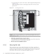
d.
Insert
the
PDU
connection
side
of
the
power
cords
through
the
top
opening
of
the
rack.
A
in
represents
the
power
cord
for
single-phase
power
feed.
B
in
represents
the
power
cord
for
three-phase
power
feed.
Figure
3-7
Inserting
power
cords
Fujitsu
M10/SPARC
M10
Systems
Installation
Guide
・
July
2015
80
Summary of Contents for M10 Series
Page 1: ...Fujitsu M10 SPARC M10 Systems Installation Guide Manual Code C120 E678 12EN July 2015 ...
Page 10: ...Fujitsu M10 SPARC M10 Systems Installation Guide July 2015 x ...
Page 156: ...Fujitsu M10 SPARC M10 Systems Installation Guide July 2015 142 ...
Page 176: ...Fujitsu M10 SPARC M10 Systems Installation Guide July 2015 162 ...
Page 208: ...Fujitsu M10 SPARC M10 Systems Installation Guide July 2015 194 ...
Page 240: ...Fujitsu M10 SPARC M10 Systems Installation Guide July 2015 226 ...
Page 252: ...Fujitsu M10 SPARC M10 Systems Installation Guide July 2015 238 ...
Page 290: ...Fujitsu M10 SPARC M10 Systems Installation Guide July 2015 276 ...
Page 310: ...Fujitsu M10 SPARC M10 Systems Installation Guide July 2015 296 ...
Page 336: ...Fujitsu M10 SPARC M10 Systems Installation Guide July 2015 322 ...
Page 368: ...Fujitsu M10 SPARC M10 Systems Installation Guide July 2015 354 ...
Page 374: ...Fujitsu M10 SPARC M10 Systems Installation Guide July 2015 360 ...