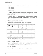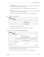
4.1 Mode Parameters
C141-C010
4-37
c. Driver Asymmetry (not supported)
This shows the amplitude difference between the assert and negate signals sent from the driver.
d. Driver Slew Rate
This shows the result obtained by dividing the size difference between assertion and negation by the
time difference between rising and falling.
The default values of the above parameters a to d are X'0000'.
A value in this field is indicated by an absolute value (2's complement) that does not affect the preset
value based on the default value. As listed below, the value is specified in 16 stages, from B'0111'
(maximum value) to B'1000' (minimum value). If a specified value cannot be supported according
to the capability of a device, the value is rounded off.
Bin (b)
Dec (d)
Remark
0111 7
Maximum
setting
0110 6
0101 5
0100 4
0011 3
0010 2
0001 1
0000 0
Default value
(recommended value)
1111 -1
1110 -2
1101 -3
1100 -4
1011 -5
1010 -6
1001 -7
1000 -8
Minimum
setting
The operation corresponding to each value depends on the vendor, so the ANSI standard does not
define the difference between actual maximum and minimum values. However, the setting does not
violate the applicable standard.
Only the REQUEST, ACKNOWLEDGE, DATA BUS, P_CRCA, and DB (P1) signals are affected
to the same degree by this setting.
Summary of Contents for 80
Page 4: ...This page is intentionally left blank ...
Page 10: ...This page is intentionally left blank ...
Page 18: ...This page is intentionally left blank ...
Page 62: ...This page is intentionally left blank ...
Page 284: ...Sense Data Error Recovery Methods This page is intentionally left blank ...
Page 296: ...This page is intentionally left blank ...
Page 298: ...This page is intentionally left blank ...
Page 308: ...This page is intentionally left blank ...
Page 309: ......
Page 310: ......


