background image

User’s manual · TFF 310 CI 


- 17 -                TFF 310 CI                 version_en_2.0               FTE maximal 

 
3. SD Backup 
This option allows saving and loading the configuration of the module in the PRO 300 programmer.  
 
 
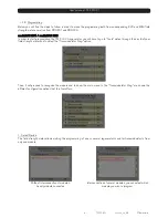
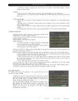
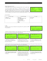
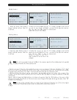
- Read from module: It stores the current configuration of the module in the memory of the programmer. The steps to 
make a correct reading of the headend are specified below: 


1. Select the option “Read from 
module” through Up/Down buttons. 
Press OK to continue  

2.  Select the position of “CFG” 
memory where you wish to save the 
current configuration of the module. 

3. A window will appear and it will let 
you know that the reading made has 
been correct 

 
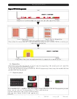
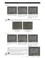
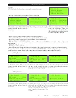
- Write to module: It loads in the module one of the configurations previously saved in the memory of the programmer. The 
steps to make a correct configuration of the headend are specified below: 


1. Select the option “Write to module” 
through Up/Down buttons. Press OK 
to continue  

2.  Select the position of the “CFG” 
memory that you wish to copy in the 
module. Please verify that the data of 
the selected memory correspond to 
the channel that you wish to copy. 

3. A window will appear and it will let 
you know that the configuration made 
has been correct 


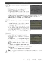
4. CAM 
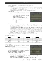
This option allows selecting which services are decrypted and enabling the 
access to the CAM parameters. 


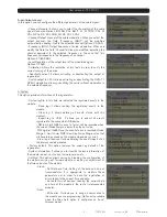
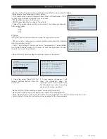
- Decrypt services: From this option you can add or remove manually the services that are being decoded by the card. 

Write to module 

 Operation finish

TFF 310 CI

Write to module 

                CFG:00 
Freq 858000
Output     Freq:474000 

TFF 310 CI

SD Backup 

1.Read from module

2.Write to module

TFF 310 CI

Read from module 

 Operation finish

TFF 310 CI

Read from module 

                CFG:00 
Freq 858000
Output     Freq:474000 

TFF 310 CI

SD Backup 

1.Read from module

2.Write to module

TFF 310 CI

CAM

1.Decrypt services. 

2.CI menu 
3.Reset CAM 

TFF 310 CI

Summary of Contents for TFF 310 CI

Page 1: ...TFF 310 CI USER S MANUAL...

Page 2: ...nges of temperature 8 Never open the device by yourself due to electric risk In case of problems go always to qualified technicians 9 Never under no circumstances open the device when connected to the...

Page 3: ...ting mode Red Phase of initializing the module 2 Operative Mode Green The system is working properly Orange At least one critical event has been recorded in the module The led will only change into gr...

Page 4: ...el and output parameters of a multiplex with a corrected error rate 1 4 Programming TFF 310 CI has two ethernet connectors In order to make the programming of the module you have to connect the corres...

Page 5: ...ols option through the key 8 of your field strength meter and to select the Transmodulator Prog option Then it will proceed to recognize the module and to show the main menu In the Transmodulator Prog...

Page 6: ...f the multiplex that you wish to tune When you modify this field the field Channel will be also modified indicating the channel equivalent to the selected frequency in the case that this frequency cor...

Page 7: ...are indicated the registered events in the module Read log It allows reading the registered events in the module Clear log It allows deleting all events stored until this moment Export log to USB It a...

Page 8: ...ork into the internal disk or in the external storage device USB 2 0 Once the option is selected a dialog box will appear and we will be able to choose among three different options Auto The Meter dec...

Page 9: ...s 1 Select the Service to remove option 2 Select one of the multiplex services you want to remove 3 Once you have chosen the service select the Add Rem button to remove the service in the multiplex Re...

Page 10: ...ured when tuning the standard definition channel it will move to its position in high definition automatically This option allows modifying manually the position of the LCN exchanging the standard pos...

Page 11: ...Ter In this option you will be able to configure the input parameters of the terrestrial signal Freq MHz Input frequency of the multiplex that you wish to tune In order to introduce the frequency pre...

Page 12: ...save the current configuration of the module 3 A window will appear and it will let you know that the reading made has been correct Write to module It loads in the module one of the configurations pre...

Page 13: ...e selected the DVB T DVB H modulator configuration you can make the assignment of the services that are going to be included in the output multiplex Adding Removing services Adding Services 1 Select t...

Page 14: ...rent time and date SW version info It allows you to visualize the basic information of the module model firmware version etc Global Update It allows carrying out the update of all the modules that are...

Page 15: ...nfiguration Output configuration Out TV In these options you can configure the output parameters of the terrestrial signal RF Channel MHz Output frequency of terrestrial modulation In order to introdu...

Page 16: ...OK the edition mode is on placing the cursor over the digit the value could be changed by means the bottoms Up Down One time finished the changes are saved pressing OK LCN The LCN function allows ass...

Page 17: ...ave the registration of errors linked to the current time and date Read LOG file It allows reading the registered events in the module 1 Select the option Read LOG file through Up Down buttons Press O...

Page 18: ...are specified below 1 Select the option Write to module through Up Down buttons Press OK to continue 2 Select the position of the CFG memory that you wish to copy in the module Please verify that the...

Page 19: ...to be removed through Up Down buttons then press OK 3 Select the service you want to delete with the Left Right keys Then press OK over Rem in order to remove it or press OK over All in order to dele...

Page 20: ...MP 310 P C d 2003520 Terrestrial antenna Installation where we get a bad signal and high error rates in the output of the antenna This signal is injected in the headend formed by 6 TFF 310 CI regenera...

Page 21: ...ode DVB T 2k 8k DVB H 2k 4k 8k Output channels C2 C69 Output connectors Female F connector Output Level 80 dBuV Regulation margin 15 dB MIX Losses 1 dB Band spurious 60 dBc Programming Interface RJ 45...

Page 22: ...6 1 32 1 4 1 8 1 16 1 32 1 4 1 8 1 16 1 32 Duration 358 4us 179 2us 89 6us 44 8us 179 2us 89 6us 44 8us 22 4us 89 6us 44 8us 22 4us 11 2us Modulation Modulation QPSK 16 QAM 64 QAM Number of bits per s...

Page 23: ...19 353 20 491 21 112 3 4 19 595 21 772 23 053 23 751 5 6 21 772 24 191 25 614 26 39 64 QAM 7 8 22 861 25 401 26 895 27 71 Useful channel capacity 6 MHz Guard Interval Modulation FEC codification 1 4 1...

Page 24: ...90 97 48 info fte it www ftemaximal com DEUTSCHLAND Zweigniederlassung Deutschland F rstenhof 68 59368 Werne Amtsgericht Dortmund HRB 21674 Ust ID Nr DE243384161 Tel 49 2389 92419 0 Fax 49 2389 92419...

Reviews: