4.6.2 S-Tronic Plus / S-Tronic Lambda control
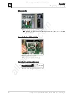
Power connection
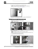
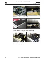
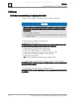
❒ Run the cable of the flue gas temperature sensor, boiler sensor, induced draught,
STL, display and door switch to the controller and connect the wiring in accord‐
ance with the operating instructions of the boiler control
➥ Tuck any extra cable into the cable duct
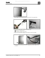
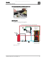
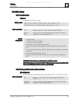
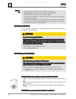
❒ Run the cable of the broadband probe, servo-motors, flue gas temperature sensor,
boiler sensor, induced draught, STL, display and door switch to the controller and
connect the wiring in accordance with the operating instructions of the boiler con‐
trol
➥ Tuck any extra cable into the cable duct
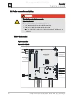
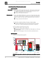
❒ Connect the components according to the power connection diagram
➥ The flexible sheathed cable must be used for the wiring; this must be of the
correct size to comply with applicable regional standards and regulations!
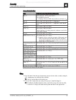
Once the individual components have been wired:
❒ Wire the mains connection in the controller box
➥ The power supply line (mains connection) must be fitted with a max. C13A fuse
by the customer!
➥ Observe the circuit diagrams in the boiler controller operating instructions.
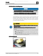
Hydraulic system
Possible, non-binding planning suggestion:
M
M
M
M
Room sensor
(Option)
External sensor
Mains supply
230V
Log wood boiler
S3 Turbo
Pump assembly
FE
Pump 1
Flow temp. sensor 1/2
Heating circuit 1/2
Mot. mixing valve 1/2
Layered tank
Domestic
hot water
HKP 0
Cold
water
Pump assembly
OE
DHW tank
Unicell NT-S
Note:
Controller S-Tronic Plus
Temp. sensor 0.1
Temp. sensor 0.2
Return sensor
With heating circuit modules
(Bus connection) up to
heating circuits are available
18
RBG 3200 /
RBG 3200 Touch
(Option)
Balancing
valve
NOTICE! It is not possible to combine the control of a return mixer with the control of a
boiler!
S-Tronic Plus:
S-Tronic Lambda:
4
Assembly
Power connection and wiring
58
Froeling GesmbH | A-4710 Grieskirchen, Industriestraße 12 | www.froeling.at
All manuals and user guides at all-guides.com

