background image

99-0073 

Rev. 00 

INSTALLATION OPERATION 

AND SERVICE MANUAL


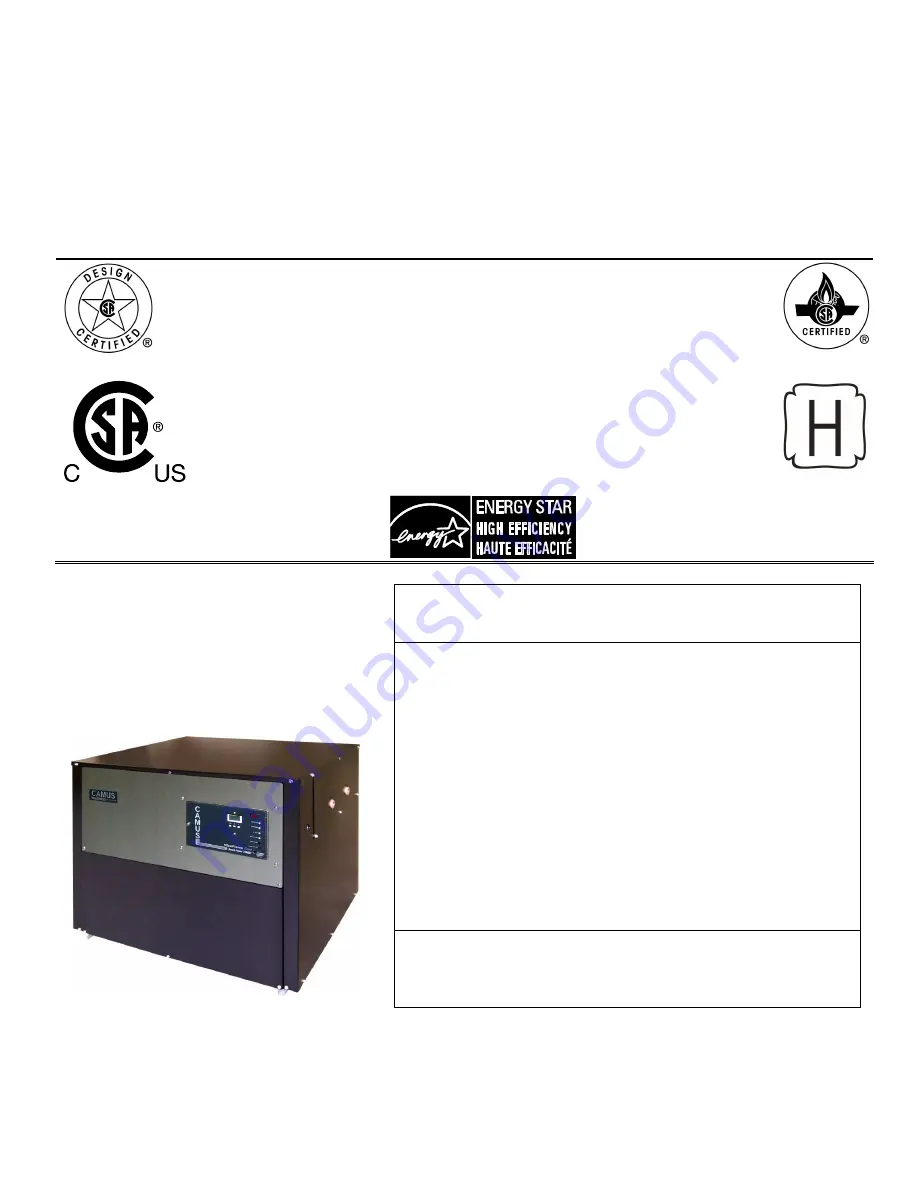
MODULATING MICOFLAME SERIES


GAS FIRED RESIDENTIAL AND COMMERCIAL COPPER TUBE 

BOILERS 


FOR HYDRONIC HEATING  

Non-Condensing Models; MFH060, 100, 150, 200, 250, 300, 400, 500, 600 

Condensing Models; MFH062, 102, 152, 202, 252, 302, 402, 502, 602                       


HOT WATER SUPPLY 

Non-Condensing Models; MFW060, 100, 150, 200, 250, 300, 400, 500, 600   

Condensing Models; MFW062, 102, 152, 202, 252, 302, 402, 502, 602 


WARNING: If the information in these instructions is not 
followed exactly, a fire or explosion may result causing 
property damage, personal injury or death 

  Do not store or use gasoline or other flammable 

vapours and liquids in the vicinity of this or any other 
appliance. 

  WHAT TO DO IF YOU SMELL GAS 

o

  Do not try to light any appliance, 

o

  Do not touch any electrical switch; do not use any 

phone in your building, 

o

  Immediately call your gas supplier from a 

neighbour’s phone. Follow the gas supplier’s 
instructions, 

o

  If you cannot reach your gas supplier, call the fire 

department. 

  Qualified installer, service agency or the gas supplier 

must perform installation and service. 


To the installer: After installation, these instructions must be 
given to the end user or left on or near the heater. 
To the End User: This booklet contains important information 
about this heater. Retain for future reference.  

CAMUS   HYDRONICS   LTD. 

6226 Netherhart Road, Mississauga, Ontario, L5T 1B7 

Summary of Contents for MFH060

Page 1: ...se gasoline or other flammable vapours and liquids in the vicinity of this or any other appliance WHAT TO DO IF YOU SMELL GAS o Do not try to light any appliance o Do not touch any electrical switch d...

Page 2: ......

Page 3: ...D CONTROLS 20 17 1 SAFETY CONTROLS 20 17 2 CONTROL PANEL 20 17 3 SETTING THE APPLIANCE TEMPERATURE CONTROLLER 21 17 4 MODES OF OPERATION 21 18 MICOFLAME CONTROL PANEL 28 18 1 GENERAL SYMBOL DESCRIPTIO...

Page 4: ...TYPICAL GAS TRAIN 52 24 ELECTRICAL DIAGRAMS 53 24 1 MF 60 300 INTERNAL WIRING CONNECTION DIAGRAM 54 24 2 MF 400 600 INTERNAL WIRING CONNECTION DIAGRAM 55 24 3 MF 60 1000 INTERNAL WIRING LADDER DIAGRAM...

Page 5: ...ing Systems and Air Supply for Appliances of the current CAN CGA B149 Installation Codes and applicable provisions of the local building codes When required by the authority having jurisdiction the in...

Page 6: ...under the boiler If the boiler is installed above the level of the building s radiation system a low water cutoff device must be installed in the boiler outlet at the time of installation Some local...

Page 7: ...9 Installation Codes and Applicable provisions of the local building codes The operation of exhaust fans compressors air handling units etc can rob air from the room creating a negative pressure condi...

Page 8: ...ons All models are supplied with a single burner Each MicoFlame is supplied with the appropriate wiring diagram showing the sequence provided as well as any special controls or options requested When...

Page 9: ...ving sequence does not proceed to completion the first safety light to remain off will indicate the cause of the problem All other lights below the problem indicator light will also remain off 6 GAS S...

Page 10: ...e common venting system is likely to be too large for proper venting of the appliances remaining connected to it At the time of removal of an existing boiler the following steps must be followed with...

Page 11: ...chimney for obstruction and clean as necessary 3 Remove burner from boiler and vacuum the heat exchanger If heat exchanger is excessively dirty it may be necessary to remove it from the boiler and was...

Page 12: ...llowing applies to outdoor installations 1 Use only factory supplied rain shields 2 Periodically check to ensure that air intake and vent cap are not obstructed 3 Locate boiler at least 3 feet away fr...

Page 13: ...ntal sidewall vent or vertical roof top terminal Terminals differ with each application The following applies to outdoor air installations 1 Use only factory supplied air intake terminal 2 Periodicall...

Page 14: ...late sizing of the venting system In applications where flue gas temperatures are lower than can support a Category II with conventional negative draft it will be determined at the venting design stag...

Page 15: ...contact of the low water cutoff is to be wired in series with the flow switch A diagnostic light will be indicated on the control display on a low flow condition Caution remove jumper when connecting...

Page 16: ...door installations a snow screen should be installed to prevent snow and ice accumulation around the appliance Regular inspections should be made to ensure that air intake and vent are free of snow an...

Page 17: ...Table is provided as a guide For application in areas known to have hard water conditions contact factory for recommendations Table 5 Flow and Pressure Drop at a Given Temperature Rise Head Loss and F...

Page 18: ...vide at least 15 PSIG in the system when cold With all air vents open run system circulating pump for a minimum of 30 minutes with the boiler off Open all strainers in the circulating system and check...

Page 19: ...natively a thermostatic mixing valve may be supplied available as a factory option Figure 6 Low Water Temperature System Adjustment procedure a Fully open bypass and outlet valves b With boiler runnin...

Page 20: ...not operate the appliance with the CHRM piped out or isolated The CHRM is mounted in the discharge of the flue products from the primary heat exchanger This allows additional heat to be absorbed from...

Page 21: ...t pipe and require a special vent adapter to increase the flue outlet diameter Sidewall and vertically vented appliances operate with positive pressure in the vent pipe and may be directly connected t...

Page 22: ...t of the appliance and is to be piped to drain in a manner similar to the appliance relief valve CHRM IN SERIES WITH PRIMARY HEAT EXCHANGER INTEGRATED LOOP The MicoFlame could be provided in condensin...

Page 23: ...19 Figure 10 Hydronic Heating Suggested Piping with CHRM Figure 11 Domestic Hot Water Suggested Piping with CHRM...

Page 24: ...perature controls reside on the control panel door Figure 12 Display Appliance Temperature Controller and Indicating LED The Boiler Temperature Controller BTC 1 for this appliance is a Camus 78 0017 S...

Page 25: ...then use the ITEM key to scroll through the settings After checking the settings allow the BTC 1 to return to normal operation on its own 17 4 MODES OF OPERATION Mode 1 Constant Temperature Control T...

Page 26: ...on until the flame is proved and then the modulating output changes the boiler burner output to maintain the programmed boiler target temperature at the system sensor If the system sensor reaches half...

Page 27: ...out Mode 4 Outdoor Reset using Boiler Inlet Sensor This mode is designed for hydronic heating Once a heat demand is present the BTC 1 turns on the appliance pump and modulates the boiler to maintain t...

Page 28: ...hen changes the modulation output to the START modulation setting and closes the Stage contacts pins 15 16 to proceed to trial for ignition The burner remains at minimum modulation until the flame is...

Page 29: ...o F 69 o C 16 170 o F 77 o C 8 174 o F 79 o C 18 190 o F 88 o C 9 192 o F 89 o C 20 210 o F 99 o C 10 210 o F 99 o C requires 500 resistor A 4 20mA signal can be converted to a 2 10VDC signal by insta...

Page 30: ...e external input signal device s terminal If the system sensor is half of the differential below the Boiler Target the BTC 1 then changes the proportional modulation output to the START modulation set...

Page 31: ...to Start Modulation level until the flame is proved and then the modulating output is adjusted to track the direct drive input signal up to the maximum of 10VDC which is equivalent to maximum input ra...

Page 32: ...field of the display To view the next item press the Item button Increase a parameter value Decrease a parameter value Levels of Access View Access to general boiler and display settings and will all...

Page 33: ...n DHW Pump Shown when DHW pump is in operation Heat Demand Shown when heat demand is present Flame Proof Shown when flame signal is proven Burner Shown when burner is on Warning Shown when an error is...

Page 34: ...Outlet Temperature Real time Outlet Temperature to Boiler 14 to 266 o F 10 to 130 o C Boiler Inlet Temperature Real time Inlet Temperature to Boiler 14 to 266 o F 10 to 130 o C Boiler Delta T Real tim...

Page 35: ...setpoint for the heating system Setpoint is controlled to the inlet sensor 70 to 220 o F 21 to 104 o C Default 120 o F 49 o C Differential Temperature To provide a modulation rate above and below the...

Page 36: ...r Inlet Temperature Real time Inlet Temperature to Boiler 14 to 266 o F 10 to 130 o C Boiler Delta T Real time temperature difference between the outlet sensor and the inlet sensor 99 to 252 o F 72 to...

Page 37: ...ntrolled to the DHW sensor OFF 70 to 190 o F OFF 21 to 88 o C Default 140 o F 54 o C DHW Differential To provide a modulation rate above and below the DHW Target Temperature For example if the value i...

Page 38: ...lable in Mode 5 14 to 266 o F 10 to 130 o C Boiler Outlet Temperature Real time Outlet Temperature 14 to 266 o F 10 to 130 o C Boiler Inlet Temperature Real time Inlet Temperature 14 to 266 o F 10 to...

Page 39: ...o 50 o F 51 to 10 o C Default 10 o F 23 o C Boiler Start Temperature Starting water temperature used in the reset ratio calculation for the heating system Typically set to the desired building tempera...

Page 40: ...rameter Name Parameter Description Parameter Range Boiler Target Temperature To provide a target setpoint for the heating system Setpoint is controlled to the inlet sensor 35 to 266 o F 2 to 130 o C S...

Page 41: ...simultaneously to view the following parameters Display Parameter Name Parameter Description Parameter Range Mode Operating mode for the boiler NOTE A complete description of each mode can be found in...

Page 42: ...e to Boiler 14 to 266 o F 10 to 130 o C Boiler Delta T Real time temperature difference between the outlet sensor and the inlet sensor 99 to 252 o F 72 to 122 o C Modulation Real time modulating outpu...

Page 43: ...e Description The control was unable to read a piece of information its EEPROM memory The control will stop operation until all settings in the Adjust menu have been checked by the installer Outlet Se...

Page 44: ...outlet sensor is operational the boiler will operate using the outlet sensor If the outlet sensor is not available and the inlet sensor is operational the boiler will operate using the inlet sensor Ot...

Page 45: ...RNER FLAMES To maintain safe operation and the greatest efficiency of the boiler check the main burner and pilot burner every six months for proper flame characteristics 19 1 MAIN BURNER The main burn...

Page 46: ...Figure 25 MicoFlame 400 600 Burner Assembly If burner characteristics do not match the above check for proper air box pressure Also look for accumulation of lint and other foreign material at fan air...

Page 47: ...needs cleaning 1 Shut off power and close main manual gas valve Allow burner to cool before removal 2 Remove access cover screws Disconnect pilot gas at bulkhead fitting Disconnect ground wire and ign...

Page 48: ...er box assembly with the metal filter cover removed to expose pilot tube Figure 26 Pilot and Burner Box Once the spark is satisfactory open the pilot gas and allow the pilot burner to light Once air h...

Page 49: ...Once satisfied replace the regulator adjustment screw cap and the elbow pressure tap plug Table 11 Gas pressures at inlet to pilot PROPANE NATURAL GAS Minimum inches W C 3 9 1 3 Maximum inches W C 9...

Page 50: ...perating conditions on the BTC 1 Controller To adjust the low fire setting Observe the Boiler Inlet Temperature Set the Boiler Target temperature so that it is 10 o F above the Boiler Inlet Temperatur...

Page 51: ...ue this procedure until combustion levels are satisfied Reset the Target Temperature to normal operating conditions on the BTC 1 Controller To adjust the low fire setting Observe the Boiler Inlet Temp...

Page 52: ...et Temperature Set the Boiler Target temperature so that it is 10 o F above the Boiler Inlet Temperature The boiler will begin to modulate to low fire as setpoint is being reached The actual modulatio...

Page 53: ...nel Differential Air Switch A differential air pressure switch is provided to prove air flow at minimum fire conditions 1 Remove the lower front jacket panel 2 Insert allen key into the switch located...

Page 54: ...more are considered seasonal operations It is recommended that before returning one of these units to service the proper operation of all controls be checked by a qualified service technician 21 LIGHT...

Page 55: ...und electrodes are positioned properly Clean with steel wool if necessary Verify that back of burner box is fully engaged into the retaining slot in the combustion chamber base 5 Pilot lights but main...

Page 56: ...52 23 TYPICAL GAS TRAIN Figure 30 MicoFlame Modulation 60 300 Gas Train Figure 31 MicoFlame Modulation 400 600 Gas Train...

Page 57: ...MicoFlame boiler will be provided with its own wiring diagram to guarantee that any options ordered with the unit are properly detailed The following diagrams 99 5085 C 99 5086 C and 99 5086 S are pro...

Page 58: ...54 24 1 MF 60 300 INTERNAL WIRING CONNECTION DIAGRAM...

Page 59: ...55 24 2 MF 400 600 INTERNAL WIRING CONNECTION DIAGRAM...

Page 60: ...56 24 3 MF 60 1000 INTERNAL WIRING LADDER DIAGRAM...

Page 61: ...57 25 EXPLODED VIEW...

Page 62: ...Leg 14 4014 2 Req d Per Unit 9 Outer Jacket Left 14 4082 14 4082 14 4082 14 4082 14 4082 14 4082 14 4032 14 4032 14 4032 10 Outer Jacket Right 14 4081 14 4081 14 4081 14 4081 14 4081 14 4081 14 4031 1...

Page 63: ...N A 14 4023 14 4023 N A 28 Burner Box Assembly 14 4079 14 4079 14 4079 14 4079 14 4079 14 4079 14 4029 14 4029 14 4029 Fan Mounting Support Staging N A N A N A N A N A N A 14 4039 01 14 4039 01 14 40...

Page 64: ...main 110V 77 0019 77 0019 77 0019 77 0019 77 0019 77 0019 77 0019 77 0019 77 0019 41 Air Inlet Hole Cover 14 4083 14 4083 14 4083 14 4083 14 4083 14 4083 14 4083 14 4083 14 4083 42 Flue Collar 14 406...

Page 65: ...standard warranty 2 Years six through ten replacement purchase price pro rated at the following schedule Year six 60 Year seven 65 Year eight 70 Year nine 75 Year ten 80 of the current list price of t...

Page 66: ...uilt water heaters and heating boilers as well as a into every single unit For more information supplier of specialty HVAC products Our service line is open 24 hours 7 days a week on our innovative pr...

Reviews: