background image

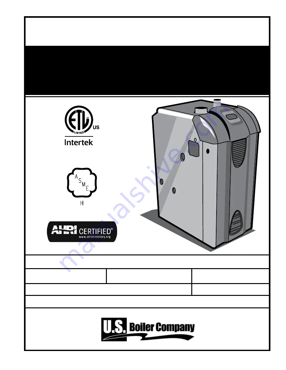
INSTALLATION, OPERATING AND

SERVICE INSTRUCTIONS FOR

ESC

ENHANCED SEALED COMBUSTION

Gas - Fired Boiler

103788-03 - 9/13

For service or repairs to boiler, call your heating contractor.  When seeking information on boiler, provide 

Boiler Model Number and Serial Number as shown on Rating Label.

Boiler Model Number


ESC_C

  Boiler Serial Number

  Installation Date

Heating Contractor

  Phone Number

Address

9700609

Price - $5.00

Summary of Contents for ESC

Page 1: ...788 03 9 13 For service or repairs to boiler call your heating contractor When seeking information on boiler provide Boiler Model Number and Serial Number as shown on Rating Label Boiler Model Number...

Page 2: ...amage If you must leave your home unattended for an extended time when outdoor temperatures are below 32 F first turn off your home s main water supply and drain the water from all pipes DO NOT BLOCK...

Page 3: ...ROPERLY relative to the heat load A grossly oversized boiler will cycle excessively and this will lead to premature failure of the boiler and its components Our warranty does not apply to damage from...

Page 4: ...l be permanently mounted to the exterior of the building at a minimum height of eight 8 feet above grade directly in line with the exhaust vent terminal for the horizontally vented gas fueled heating...

Page 5: ...al 1 Air Intake Terminal 1 Drain Valve q ESC3 ESC4 P N 102648 01 q ESC5 ESC6 P N 102648 02 q ESC7 P N 102648 03 q ESC8 ESC9 P N 102648 04 4 Instruction Envelope 103787 01 q Instruction Operation Manua...

Page 6: ...12 41 1 1 3 3 ESC4C 33 15 41 1 1 3 3 ESC5C 33 18 41 1 1 3 4 ESC6C 33 21 41 1 1 3 4 ESC7C 33 24 41 1 1 3 5 ESC8C 33 27 41 1 1 4 5 ESC9C 33 30 41 1 1 4 5 Dimensions Weights and Connections Electrical Re...

Page 7: ...7 Figure S 1 Minimum Clearances to Combustibles SPECIFICATIONS continued...

Page 8: ...5 9 Check for gas and water leaks 18 10 Perform startup checks and adjustments 19 Annual Maintenance Checklist 21 Troubleshooting 23 Repair Parts List 29 Internal Wiring 37 Appendices A Combustion Air...

Page 9: ...INSTALL ON CARPET This may cause a fire INSTALLING THE BOILER NEAR A SOURCE OF FLAMMABLE LIQUIDS or gases may cause fire or explosion CLEAN BURNERS DAILY if operating the boiler in a dusty environment...

Page 10: ...elease of deadly carbon monoxide CO into the home Observe all general venting guidelines provided in Appendix B Venting Additionally Follow all instructions in Appendix B 2 Direct Vent or B 3 Power Ve...

Page 11: ...rect Venting Special Instructions for Stainless Steel Venting Vertical Installations Specifically 1 Install fire stops and wall thimbles 2 Install vent piping and vert terminal 3 Install condensate li...

Page 12: ...igure 5 a 3 Pipe from the street elbow through the left jacket panel and complete drip leg as shown Figure 5 a 6 Connect Boiler Water Piping General system piping guidelines are included in Appendix D...

Page 13: ...D 6 Connect Boiler Water Piping continued 9 See Figure 6b for suggested near boiler piping of IQ Options 10 Maintain minimum 1 2 clearance between water piping and combustible construction 6 b Item D...

Page 14: ...nd in accordance with requirements of authority having jurisdiction or in the absence of such requirements with the National Electrical Code ANSI NFPA 70 WIRE AN ADDITIONAL SAFETY LIMIT such as a low...

Page 15: ...to Close 13 Soft Lockout 14 Hard Lockout 15 Waiting for Limit to Close 16 Flame Present Out of Sequence 17 Self Test For example when the I key is pressed on the control until bt is displayed it will...

Page 16: ...The Outdoor Reset IQ Option Card reduces the Operating Setpoint to regulate heat delivery increase home comfort and save energy Refer to the Appendix I for additional information The High Limit setpo...

Page 17: ...h no delay DHW on tt2 140 Start after 2 minute delay DHW on dh 140 Start with no delay DHW on dh 140 Start with no delay 5 Start Temperature Amount of Heat available is calculated by taking the differ...

Page 18: ...g Zone is detected by sensing a voltage on the DHW terminal Table 8c DHW Terminal Function Selection Second Heating Zone Parameter dh_ tt2 Call for Heat Circulator Status T T Input DHW Input System Ci...

Page 19: ...and main burner flames appear clean and blue 11 Adjust the high limit setting to its minimum level see Programming High Limit in Section 8 q Boiler shuts off when temperature gage reads within 15 F of...

Page 20: ...20 Figure 10 d Operating Instructions 10 Perform Startup Checks and Adjustments continued...

Page 21: ...d respirator 2 Long sleeved loose fitting clothing 3 Gloves 4 Eye Protection Take steps to assure adequate ventilation Wash all exposed body areas gently with soap and water after contact Wash work cl...

Page 22: ...ler flue passages 1 Remove vent pipe 2 Remove top panel and hood 3 Remove canopy 4 Examine all flue passageways Using bristle flue brush and vacuum remove any soot or obstructions 5 Use installation p...

Page 23: ...e Before replacing a component try to rule out all other possible causes 5 When checking voltage across wiring harness pins be careful not to insert the meter probes into the pins Doing so may damage...

Page 24: ...in excess of 40 mph Replace blower Err 32 Temperature Sensor Failure Temperature sensor or interface failure open or short connection increased connection resistance dual sensor mismatch or control h...

Page 25: ...Display 3 Boiler is On But Circulator is Off Display Status Recommended Corrective Action StA 8 Burner on Circulator off Domestic Hot Water DHW Priority Forcing Circulator Off When there is a DHW heat...

Page 26: ...ed and the one hour time delay is completed Boiler can be restarted sooner than the time delay by entering Adjustment Mode and selecting the reset button see Adjustment Mode instructions or by cycling...

Page 27: ...than once to clear the pilot supply tubes of air b If no gas flow check the following 24 volts across PV and MV PV at gas valve if voltage ok replace defective gas valve Check for break in wiring harn...

Page 28: ...t and reinstall card If problem persists replace card Err 5 Limit Output OFF in ON State Check limit string wiring replace the IQ Option Panel Err 6 Incorrect Wiring Check boiler wiring Err 7 Internal...

Page 29: ...2 4 71107002 5 71107002 6 71107002 7 71107002 8 71107002 All ESC Repair Parts may be obtained through your local U S Boiler Company Wholesale distributor Should you require assistance in locating a U...

Page 30: ...a Level 102594 03 102594 04 102594 05 102594 06 102594 07 102594 08 102594 09 Canopy Assembly High Altitude 102594 13 102594 14 102594 15 102594 16 102594 17 102594 18 102594 19 2B Canopy Gasket Kit 6...

Page 31: ...61807061 61807071 61807081 61807091 3D Base Front Panel 102705 03 102705 04 102705 05 102705 06 102705 07 102705 08 102705 09 3E Burner Access Panel 102707 03 102707 04 102707 05 102707 06 102707 07 1...

Page 32: ...fold 82207071 82207081 82207091 4C Burner Orifices Natural Gas 49 4 822709 6 822709 8 822709 10 822709 12 822709 14 822709 16 822709 Burner Orifices LP Gas 56 4 822707 6 822707 8 822707 10 822707 12 8...

Page 33: ...ly 61807032 61807042 61807052 61807062 61807072 61807082 61807092 5B Air Box Door 71807034 71807044 71807054 71807064 71807074 71807084 71807094 5C Combustion air diffuser N A 71807049 71807059 718070...

Page 34: ...Control 103661 01 6B IQ Option Panel 102291 01 6C Transformer 102516 01 6D Temperature Sensor 102411 01 6E Differential Pressure Switch Sea Level 0 4999 80160762 80160761 80160760 80160759 80160760 H...

Page 35: ...102588 04 102588 05 102588 06 102588 07 102588 08 102588 09 7E Jacket Top Panel 102586 03 102586 04 102586 05 102586 06 102586 07 102586 08 102586 09 7F Jacket Front Door 102661 03 102661 04 102661 0...

Page 36: ...2 01 8C Circulator Wiring Harness 6130701 8D 30 PSI Relief Valve 81660363 8E Drain Valve 102802 01 8F Vent Terminal 8110701 8110702 8G Vent Connector 8110703 N A 8H Vent Tee AL294C 3 N A 8116310 N A 8...

Page 37: ...37 Internal Wiring Figure IW 1 Wiring Diagram...

Page 38: ...38 Internal Wiring continued Figure IW 2 Wiring Diagram...

Page 39: ...39 Figure IW 3 Multiple Zone System with Zone Circulators Internal Wiring continued Figure IW 4 Multiple Zone System with Zone Valves...

Page 40: ...N O COM N C ZONE 4 RELAY DHW CIRCULATOR SUPPLIED BY OTHERS JUMPER 3 4 2 WIRE ZONE VALVE NO END SWITCH 2 WIRE ZONE VALVE NO END SWITCH 1 4 WIRE ZONE VALVE POWER OPEN SELF CLOSING JUMPER 3 4 PRIORITY Z...

Page 41: ...air to the boiler room Proceed to Step 6 Is the boiler located in a building of unusually tight construction 5 If the answer to all of the three questions below is yes then you must provide outdoor a...

Page 42: ...nce remaining connected to the common venting system placed in operation while the other appliances remaining connected to the common venting system are not in operation 1 Seal any unused openings in...

Page 43: ...ven 7 feet above grade if located adjacent to public walkway Do not install over public walkway where local experience indicates appliance flue gas vapor or condensate creates a nuisance or hazard 2 M...

Page 44: ...through wall 3 24 thick Figure B 2 Approved Terminal Locations Planning Vertical Installations 1 Install fire stop where vent and air intake passes through floors ceilings or framed walls The fire sto...

Page 45: ...is required there are two options 1 Select adjustable length pipe from Table B 1 The pipe adjusts 7 from 12 to 19 Or 2 Cut the non gasketed end of a standard straight length Make a square cut and fil...

Page 46: ...e Length ft x 7 equiv ft e Total a b c equiv ft Total a b c d e equiv ft Total length cannot exceed 50 equivalent feet length ESC3C through ESC7C or 40 equivalent feet ESC7C ESC8C Vent and combustion...

Page 47: ...e wall using screws or nails 3 Maintain 12 separation between vent and intake terminals Where the intake air pipe penetrates the external wall seal the opening with weatherproof sealant Figure B 4 4 T...

Page 48: ...the boiler 1 Install vent and intake piping per Figures B 6 thru B 8 2 Install the storm collar onto the vent pipe immediately above the flashing 3 Apply Dow Corning Silastic 732 RTV Sealant between...

Page 49: ...ent Air Intake Piping to maintain minimum vertical X and minimum horizontal Y distance of twelve 12 inches from roof surface Allow additional vertical X distance for expected snow accumulation APPENDI...

Page 50: ...50 Figure B 8 Vertical Air Intake Piping for Direct Venting APPENDIX B2 Direct Venting continued Special Instructions for Stainless Steel Direct Vent continued...

Page 51: ...and the Table C 1 Maximum Capacity of Schedule 40 Pipe in Cubic Feet Per Hour CFH Length Feet 0 3 w c Pressure Drop 0 5 w c Pressure Drop 1 1 1 1 10 132 278 520 1050 175 360 680 1400 20 92 190 350 73...

Page 52: ...r and its individual shut off valve from the gas supply piping 2 When testing at psig or less isolate boiler from gas supply piping by closing boiler s individual manual shut off valve 3 Locate leaks...

Page 53: ...If filling the boiler with softened water test regularly the water softener regularly to ensure that brine solution is not entering the boiler s water supply 2 Lime scale 1 Repair leaking pipes fittin...

Page 54: ...diator and when required by local code i The following system diagrams are intended to provide a minimum level of guidance for a successful and trouble free installation of the boiler in common applic...

Page 55: ...55 APPENDIX D System Piping continued Figure D 2 Recommended Water Piping for Zone Valve Zoned Heating Systems...

Page 56: ...56 APPENDIX D System Piping continued Figure D 3 Recommended Water Piping for Circulator Zoned Heating Systems...

Page 57: ...onvector and repeat procedure until all convectors in the loop are purged of air 10 Close the opened zone valve or shut off valve for the zone being purged of air 11 Open the zone valve or shut off va...

Page 58: ...s valves adjustment screw clockwise to increase manifold pressure or counterclockwise to decrease manifold pressure Figure F 2 Several turns may be required Do not force the adjustment screw Do not ex...

Page 59: ...ler at its rated high fire input 4 With the analyzer check the CO2 or O2 CO and temperature of the flue gases exiting the boiler 5 For two stage or modulating boilers also check the CO2 or O2 CO and t...

Page 60: ...e of the problem Table 5 provides a list of boiler status codes that are reported Refer to the Troubleshooting Section for more information APPENDIX H OPERATION Status Codes displayed in STA Mode Stat...

Page 61: ...onal Outdoor Air Reset Card is installed in the IQ Option Panel the Operating Setpoint temperature is automatically adjusted according to the outdoor temperature For example as the outdoor temperature...

Page 62: ...etpoint The Operating Setpoint is set to the DHW Setpoint when the Outdoor Reset Option Card DHW input is energized This setpoint is set equal to the Indirect Water Heater manufacturer s recommended w...

Page 63: ...reset curve to save energy while the home is in a reduced room temperature mode Honeywell VisionPro IAQ Setback Thermostat Honeywell P N TH942lc1004 The Display Kit provides a 3 5 LCD multi color Tou...

Page 64: ...Instructions Unit Pack 102292 01 Aquastat IQ Option Card 130 220 Deg F Manual Reset for use with IQ Option Panel less well Less Sensor 102293 01 Aquastat IQ Option Card 130 220 Deg F 15 Deg F Adjustab...

Reviews: