background image

                                                   Service-Manual_artista_630_640_english_V4.01_032069_50_04.doc 

58


98 

99 

100 

101 

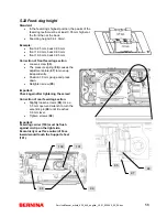
5.22 Feed-dog height 

Standard: 


In the feed-dog's highest position, the peaks of the 
feed-dog teeth must be at least 0.05 mm higher at 
the front than at the back. 


Feed-dog height (0.9-1.0mm). 


Example: 


front 0.95 mm, back 0.90 mm 


front 1.00 mm, back 0.90 mm 


front 1.00 mm, back 0.95 mm 


Correction of front feed-dog section 

 Loosen 

screw 

(

95

). 


The pressure spring (

96

) causes the 

adjustment plate (

97

) to move up 

independently. 


Position 1.0 mm gauge and press 
down. 


Retighten screw (

95

). 


Important: 
Check again after tightening the screw! 
 
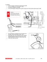
Correction of rear feed-dog section: 


Slightly loosen screws (

98

). Use a 

5.5 mm open-end wrench to turn the 
eccentric pin (

99

) until it reaches  

0.9 mm level.


 Tighten 

screws 

(

98

). 


Important: 
Feed-dog carrier (100) must lie flush 
against circlip on the right side. 
Eccentricity must face outward! Face 
inward would touch the Support sheet 
(101). 


95 

97

96

Summary of Contents for Bernina artista 630

Page 1: ...Service Manual_artista_630_640_english_V4 01_032069_50_04 doc 1 Service Manual artista 630 640 Version 4 Fritz Gegauf Ltd BERNINA sewing machines 8266 Steckborn Switzerland ...

Page 2: ...ies either those delivered with the machine or purchased afterwards These are the following Mains cable Foot control unit Buttonhole foot Presser foot 1 Bobbin case with bobbin Other accessories BERNINA stitch length regulator BSR foot if applicable The Service Manual and Instructions are protected by copyright laws These documents are delivered exclusively to the recipient It is forbidden to copy...

Page 3: ...t touch the L Print and S Print until about 30 seconds after the main voltage has been switched off This is the time required for the capacitors to discharge Warning The sewing embroidery computer may only be connected to the mains supply when the chassis covers are mounted Work on the L Print S Print and mains cable may only be carried out when the mains plug has been removed from the mains suppl...

Page 4: ... shaft 41 4 23 artista 630 upper thread tension 41 4 24 artista 640 upper thread tension 42 4 25 Thread take up lever thread take up lever crank needle bar and link piece 43 Chapter 5 Adjustments 44 5 1 Tensioning the drive belt 44 5 2 Tensioning the base shaft belt 44 5 3 artista 640 hook drive belt tension 45 5 4 Bobbin winder 45 5 5 Position of the head frame plate 46 5 6 Presser foot fixation ...

Page 5: ...pping motor 84 4d All stepping motors 84 4f Stitches per minute SPM calibration 85 4g Standard SPM stitches per minute speed 86 4h Calibrating the SSU Start stop unit 86 4i Standard SSU speed 86 4j Automatic start stop 87 4k Winder motor 87 4l Basting magnet artista 640 87 4m Thread cutter clamping magnet artista 640 88 4n Thread cutting process artista 640 88 6 7 Menu 5 Adjustments 89 5a Sewing o...

Page 6: ...ur workstation 3 Only open ESD protective packaging at your ESD proof workstation while wearing an earthing wristband Electronic components must be placed on conductive table mats only Packing is carried out under the same conditions 4 Only use conductive plastic foil pouches and ESD transport boxes for dispatching electronic components even if the components might be faulty 5 Treat faulty PCBs th...

Page 7: ...doc 7 1 5 Tools and gauges Required tools and gauges commercially available not available from BERNINA Multimeter IC Extraction tool and TORX screw driver sizes No 6 8 9 10 12 15 20 and 25 1 2 3 4 5 6 7 8 9 10 11 12 13 14 15 16 17 18 19 20 21 24 23 22 25 26 27 ...

Page 8: ...rvice cable 50mm 30 pol 13 001 356 50 00 Angular pinning tool 27 Commercially available Composite Tweezers disconnecting cables 14 007 937 50 00 Pinning tool base shaft 031 950 70 00 BERNINA USB Stick 64MB 1 6 Where and how to use the service cables 25 and 26 Where to use In order to have the artista 630 and 640 machines under power whilst the covers have been taken off it is necessary to use the ...

Page 9: ...6 26 Total number of decorative stitches 145 189 Alphabets 4 5 Eyelets 2 2 Total number of stitch patterns 250 300 Functions Automatic basic settings yes yes Display of recommended optimum settings yes yes Display of selected stitch on display on display Clear clr button yes yes Balance electronically electronically Sideways mirroring yes yes Permanent reverse sewing yes yes Memory mem yes yes Pat...

Page 10: ...ithout accessories lbs approx 9 7 approx 21 approx 9 7 approx 21 2 2 Cleaning Remove covers and clean Electrostatic charging may occur during cleaning To prevent this use antistatic office equipment cleaning agents We use and recommend BASF s SURFACE CLEAN surface cleaner It forms a protective film against static electricity and is suitable for both plastic and metallic surfaces Inside parts Dust ...

Page 11: ... Motor SL Motor SP S Print S Print S Print Mains Switch Mains Plug L Print Main Motor Drive USB Host EMB Foot Control EMB Module Foot Control Unit Sensor Feed Dog Drop Lower Thread Sensor Main Motor 30 V DC LCD Background Lighting Touch Screen RET Upper Thread Sensor CFL Background Light Converter S D R A M Flash FPGA Buttonhole Sensor Presser Foot Sensor Clamping Magnet Sensor BSR Sewing Light S ...

Page 12: ... Pole yellow Upper thread tension motor 2 Pole black Presser foot position micro switch 4 Pole white Stitch width stepping motor 4 Pole Red BSR sensor 4 Pole white Buttonhole sensor 3 Pole red Presser foot pressure control 2 Pole white Clamp magnet 4 Pole yellow Winder motor 5 Pole white Threader PCB and basting magnet 30 Pole white S Print 4 Pole blue Stitch length stepping motor 10 Pole white S ...

Page 13: ...ct the connecting cables when the machine is powered 4 Pole blue Stitch length stepping motor 30 Pole white S Print 2 Pole black Presser foot position micro switch 4 Pole white Stitch width stepping motor 4 Pole Red BSR sensor 4 Pole white Buttonhole sensor 3 Pole red Presser foot pressure control 4 Pole yellow Winder motor ...

Page 14: ...nglish_V4 01_032069_50_04 doc 14 P Print artista 630 640 reverse side Note Never connect or disconnect the connecting cables when the machine is powered Sensors Upper thread sensor L Print L Print 8 pole white S Print 7 pole Ret Print ...

Page 15: ... by ohmmeter or continuity tester beeper Set measuring instrument to beeper or Ohm area Check each cable wire This involves placing the measuring tips on the top of the connector against the metal cutters to check each wire against the other Each wire individually If the wire is OK Ohm on the ohmmeter beep signal on beeper Defective wire Ohm on Ohmmeter no beep signal on beeper interruption Each w...

Page 16: ... embroidery computer the stepping motors may be in any given position The microcomputer control memory may also have any given value The stepping motors are moved to their pinning position by means of a command from the microcomputer to give a defined situation This position is then registered and set to zero in the memory This zero position then allows any stitch program to be selected and sewn T...

Page 17: ...If a fuse blows this is always for a reason The cause must be identified and removed An original replacement fuse of the correct rating must be used It is essential to test the functions on replacing the fuse The L Print and S Print are connected via an 8 pin ribbon cable Fuse F 2 T 3 15 A Item no 031 999 50 00 Fuse F 3 F 4 A Item no 031 999 50 01 S Print The S Print is manufactured according to S...

Page 18: ...n service program 3 Mechanical checks Remove all covers Cleaning of mechanical parts Check bevel gears for wear and tear Checking of Main shaft play Base shaft play Thread take up lever Needle bar support Feed dog Functioning of bobbin case hinge Functioning of upper and lower thread tension Lubricate the machine 4 Sewing checks Sewing off using the following Functioning of the Quick reverse butto...

Page 19: ...rn Is the stitch formation symmetrical The stitched outline in the 9 and the leaf must correctly meet up 6 Any other stitch e g Honeycomb stitch Is the stitch formation symmetrical Is the thread feed regular Is the fabric free from puckering 7 Buttonhole Standard buttonhole Is the stitch formation symmetrical Are the beads of equal length Is the feed correct Automatic buttonhole Is the stitch form...

Page 20: ... 5 2 Remove head cover Attention The a 640 must have the head cover refitted when sewing off Rear cover 1 Remove screw 6 2 Remove screws 7 3 screws Remove L Print cable 3 Remove rear cover 4 The covers are linked with clips at the points B Slightly press against the points to de clip them Note Be sure not to squash the CFL and buttonhole sensor cables in the head area A when refitting the covers B...

Page 21: ...r stop 5 Lift cover over upper thread tension adjusting disc and pull out 6 8 Disconnect connectors 9 12 9 main motor S Print 10 S Print voltage supply 11 P Print S Print 12 CFL S Print 4 2 Thread pre tensioner Disassembly 1 Remove rear cover 2 Remove screw 123 3 Remove thread pre tensioner 124 and replace Assembly 1 Refit thread pre tensioner 124 2 Refit screw 123 3 Refit cover 4 Carry out a func...

Page 22: ...ht in the guide until clip 126 engages 2 Important Don t forget to refit spring 127 and ball 128 3 Refit L Print cover 4 Refit cover Carry out a functional check 5 Sew off 4 4 Horizontal spool pin and rear thread guide eyelet Disassembly 1 Remove rear cover 2 Pinch clip 129 and pull spool pin out to the back Replace 3 Replace thread guide eyelet 131 Assembly 1 Position thread guide eyelet 131 2 Mo...

Page 23: ...and remove 4 Carefully prise lock 133 apart using a screwdriver Push pin 134 out to the right and remove 5 Remove handle 135 and replace Assembly 1 Insert handle 135 2 Slide pin 134 in from the right until it engages 3 From the left move pin 132 to the stop 4 Refit spool pin 130 and thread guide eyelet 131 5 Refit cover 6 Carry out a functional check 7 Sew off 133 132 134 135 130 ...

Page 24: ...d pull magnifying glass holder 137 downwards and out Replace 3 Pinch clip 138 and pull thread cutter 139 downwards and out Replace Assembly 1 Move thread cutter 139 upwards in the guide until clip 138 engages 2 Move magnifying glass holder 137 upwards in the guide until clip 136 engages 3 Refit head cover 4 Carry out a functional check 5 Sew off 137 139 136 138 ...

Page 25: ...own the locking clip to disconnect the ribbon cable 25 from the touch screen 10 Carefully slide down the locking clip to disconnect the ribbon cable 24 from the LCD 11 Disconnect LCD backlighting plug 27 Note Pull only on the plug and not the LCD lighting cable because the CFL tube may break 12 Remove screws 16 4 screws 13 To remove lift S Print 22 from beneath and pull out from under pin 14 14 Gu...

Page 26: ...bles 24 and 25 through the opening 6 Make sure to insert the shaft faces of the stitch width and stitch length adjusting knobs into the respective SW SL potentiometer openings on the S Print 7 Tighten screws 16 to fasten S Print 8 Reconnect cables 21 24 25 27 and lower thread indicator on artista 640 Make sure that the ribbon cables sits correctly and carefully close the locking clip 9 Refit front...

Page 27: ...f the P Print can be seen in the PCB s cut out disc must lie centred in the light barrier 4 Reconnect plugs 141 148 5 Refit covers 6 Carry out a functional check 7 Sew off Connectors 141 presser foot lifter sensor 142 stitch width stepping motor 143 presser foot pressure sensor 144 winder motor 145 S Print 146 2 connectors on artista 640 s S Print stitch length stepping motor 147 buttonhole foot s...

Page 28: ...cket 155 6 Remove screws 151 7 Lift L Print 152 from top and pull out of guide 154 8 Replace L Print 152 Assembly 1 Refit L Print 152 and screws 151 they are shorter than screws 18 2 Re engage switch 156 and socket 155 3 Refit L Print cover 103 4 Refit screws 18 and covers 5 Calibrate speed 6 Carry out a functional check 7 Sew off Fuse F 2 T 3 15 A Item number 031 999 50 00 Fuse F 3 T 4 A Item num...

Page 29: ...e of safety regulations the high voltage power is switched off If the screen is not lighting check the CFL first 4 11 Presser foot lifter sensor micro switch Disassembly 1 Remove covers 2 Remove adjusting wheel lock 161 3 Remove carefully the adjusting wheel 162 so that the spring loaded pressure lever remains in place 4 Remove upper thread tension p 40 41 5 Disconnect plug 141 from P Print 149 se...

Page 30: ... plug 141 to P Print 149 4 Turn hopper mechanism lever into position then tighten screw 88 slightly 5 Use thread take up lever to swing link shaft up Then refit clamp with screw 163 To clear the thread take up s play push link shaft slightly to the right 6 Refit upper thread tension p 40 41 7 Set darning foot height p 46 8 Refit adjusting wheel 162 and safety stop 161 Make sure the pressure lever ...

Page 31: ...onal check 9 Sewing off 4 13 Main motor complete unit only Disassembly 1 Remove covers 2 Pull motor connection cable out from guide channel remove clip 3 Remove ventilator fan 24 which is press fitted onto motor shaft 4 Remove the two securing screws 25 5 Remove the motor Assembly 1 Fit new motor and fasten with the two securing screws 25 2 Adjust belt tension Check for ease of movement 26 3 Refit...

Page 32: ...f the adjusting wheel 3 Refit adjusting wheel lock 161 4 Refit CFL p 28 5 Fit pinion in toothed segment centre but don t fasten it yet 6 Reconnect motor Refit front cover 7 Attach front cover connect S Print to both P Print and L Print 8 Connect mains plug 9 Start machine in service program mode 10 Select pinning positions in SP test 4e p 83 11 Pinion distance to metal plate is 0 5 mm 12 Pin pinio...

Page 33: ...ook tension springs 30 34 and remove P Print plug 146 p 26 4 Remove both securing screws 35 of the motor bracket 36 5 Remove bushing support 37 including screws 37a and crankshaft 6 Replace crankshaft if necessary 7 Remove motor bracket 8 Remove drive pinion 40 including screw 40a 9 Remove the two securing screws 41 p 26 10 Replace stepping motor 28 35 39 34 33 36 35 29 38 37a 31 167 30 37 32 ...

Page 34: ...nion 40 to stop position and tighten screw 40a 6 Switch machine off remove 0 5 mm gauge and refit rubber sleeve a 7 Slide crankshaft into spherical bearing place toothed segment parallel picture B then place it against stepping motor stop 8 Slide stitch length transmission crankshaft and motor bracket together into the machine and fasten with two screws 35 9 Secure crankshaft with bushing support ...

Page 35: ...tentiometer 166 2 Refit screw 165 3 Place cable 163 correctly in guide 4 Reconnect plug 143 5 Refit metal guide 164 6 Refit adjusting wheel 162 Make sure the pressure lever fits into the spring into the potentiometer and the guide of the adjusting wheel 7 Refit adjusting wheel lock 161 8 Refit covers 9 Carry out a functional check test 5e p 91 10 Sew off 4 17 Winder motor Disassembly 1 Remove cove...

Page 36: ... 43 including securing screws 44 4 Remove both bushing supports 45 5 Loosen screw 46 and belt tensioner 47 Retighten screw 46 6 Remove securing screws 49 and swing shaft bearing 49 down Take care not to lose ball and springs 7 Loosen securing screws 35 on stitch length stepping motor bracket 8 Lift base shaft up to the left and guide out to the right 9 Replace base shaft 35 45 45a 35 43 34 33 44 ...

Page 37: ...en screws 35 to fasten stitch length stepping motor 5 Place drive belt on bevel gear and tighten belt tensioner 47 with tension spring Tighten screw 46 6 Refit shaft bearing 48 and adjust to a 0 1 0 3 mm springing by tightening screw 49 7 Remove pinning gauges 8 Refit feed dog drop unit and tighten securing screws 44 9 Re hook tension springs 30 34 10 Adjust hook synchronization p 50 11 Refit main...

Page 38: ...race ring 6 Place V notched paralleling gauge on feed dog shaft 14 and 15 on p 38 and hook race ring 16 and 17 on p 38 7 Slightly press paralleling gauge against the four supporting points Check position of centering gauge 8 Retighten screws 12 Check the position again after tightening the screws 9 Slide hinge pin for hook cover back in Tighten screws 52 10 Set toothed rack to the left needle bar ...

Page 39: ...gth to stop 3 Set needle bar to highest position 4 Position centering gauge in stitch plate holder 5 Place V notched paralleling gauge on feed dog shaft 14 and 15 and stitch plate holder 16 and 17 6 Slightly press paralleling gauge against the four supporting points Check position of centering gauge 7 Retighten screws 12 Check the position again after tightening the screws 8 Slide hinge pin back i...

Page 40: ...move 9 Remove two cutting blade screws 10 Replace cutting blade 11 Check hook for smooth operation clean and lubricate 12 Remove any burr from hook tip hook body and retainer Assembly 1 Position new cutting blade and tighten the two screws 2 Slide drive belt in 3 Slide hook into drive belt from the front and tighten flat headed screw 7 4 Refit belt tensioner and tighten drive belt is tightened aut...

Page 41: ...note the pinning positions 3 Refit the shaft bearing bracket 48 0 1 0 3 mm play between bearing shaft and bracket Adjust with screw 47 4 Tension drive belt turn hand wheel back by a half rotation tighten screw 49 5 Adjust synchronisation p 50 CB and 52 RH 6 Refit main motor p 30 7 Refit covers 8 Calibrate speed Service Program test 4f p 84 9 Carry out a functional check 10 Sew off 4 23 artista 630...

Page 42: ...ng screws 58 6 Remove thread tension unit Assembly 1 Fit new thread tension unit and tighten securing screws 58 and 21 2 Refit link clip 20 3 Note the position of the thread tension release 4 Set the stitch width limiter 73 with screw 74 5 Reconnect thread clamp magnet plug 6 Refit rear and front covers 7 Set thread tensioner p 63 64 8 Set regulator spring p 65 9 Check thread tension release mecha...

Page 43: ... right 11 The link piece can be replaced by loosening the screw and sliding it off the shaft 12 Replace thread take up lever link piece needle bar and or crank Assembly 1 Refit link piece 2 Put thread take up into link piece 3 Put crank into thread take up and washer into balance piece 4 Put thread take up crank into crank guide piece 65 5 Slide needle bar back into needle bar support Tighten scre...

Page 44: ...be absolutely straight 130 705 H TCN When servicing always use genuine BERNINA parts and accessories either the ones supplied with the machine or purchased afterwards These are the following Mains cable foot control buttonhole foot bobbin case with bobbin BSR foot if applicable and other accessories 5 1 Tensioning the drive belt Slightly loosen the securing screws 25a Position the motor as require...

Page 45: ...urn screw 80a in or out as appropriate Correcting the bobbin filling Turn screw 80b in or out as appropriate Note Use the bobbin adjustment gauge as described below to check the filling level Item 031 939 7000 1 Fit the gauge over the bobbin winder spindle 2 Turn the gauge until the flat on the gauge is exactly opposite to the switch lever of the winder device 3 Activate the switch lever as you wo...

Page 46: ...h plate Tighten screw 1a Remove presser foot and insert a size 90 needle Turn screw 2a in or out to center the needle in the stitch hole of the needle plate 5 6 Presser foot fixation Standard Using a new presser foot the tension pin 81 should be positioned one third to halfway along tension lever 82 The presser foot sole 83 should be positioned parallel to the markings on the stitch plate Correcti...

Page 47: ...161 Check functioning 5 8 Darning foot height Standard Attach darning foot no 9 or drop shaped foot no 26 Drop feed dog Turn the handwheel until the presser foot bar reaches its lowest position Use gauge 87 to check distance 0 5 mm between stitch plate and darning foot sole Correction Remove adjusting wheel lock 161 Remove carefully the adjusting wheel 162 so that the spring loaded pressure lever ...

Page 48: ...width on the artista 640 Correction Slightly loosen securing screw 71 Use eccentric key 001361 70 00 in cut out 72 to adjust needle bar support until the prescribed needle position in the stitch plate is reached Retighten screw 71 5 10 Stitch width limiter Standard Power machine Set to maximum stitch width Needle bar support in needle position left and right must be equally distributed in the limi...

Page 49: ...istances are within the mentioned tolerances Attention The thread positioning plate must be pushed to the rear against hook race ring when tightening the screws 5 12 Position of driver in hook race of artista 630 Basic position of driver see page 37 Standard The hook driver should be 0 1 0 15mm behind the front edge of the hook race See picture A for measuring method Correction Loosen driver shaft...

Page 50: ...l to check the individual zigzag stitches and the thread cutter for proper functioning on replacing the bobbin case retainer or the hook Standard Distance of 0 3mm from bobbin case carrier thread passage play picture 1 Top edge of bobbin case retainer nose must be flush with maximum radius of bobbin case carrier picture 2 Correction Remove stitch plate Loosen securing screw 12 If necessary move bo...

Page 51: ...drive gear shaft 48b so far as to be out of mesh Pin hook drive crank Push the drive gear base shaft back into mesh in such a way that the shaft can be pinned Important Cylinder flute edge must face front Refit ball bearing 48 and screw 49a Use screw 49 to adjust a springing movement of 0 1 0 3mm Important Turn the hand wheel 1 revolution and test in 4 different positions Note Drive gear and lift ...

Page 52: ...haft and hook drive crank Remove covers Pin needle drive balance piece and stitch width stepping motor in center needle position Loosen two screws 105 on toothed rack guide piece 106 Use eccentric key 001361 70 00 to adjust toothed rack until hook point is flush with right needle edge front view Retighten screws 105 Refit covers Carry out a functional check Sewing off Note The drive belt tension s...

Page 53: ...lance piece Rotate base shaft until it can be pinned Base shaft cylinder cam flute must face the front Tighten the two screws 78 Standard Needle hook tip pinning position Remove covers Pin needle drive balance piece pinning tool 030430 51 00 stitch width stepping motor and base shaft needle position center With rear view the hook tip must be flush with the right hand needle edge Rear view 78a 78 a...

Page 54: ...ng tool 030349 70 00 Turn hook via drive belt flange until hook tip is flush with right hand needle edge rear view Retighten the two hook drive belt flange screws 20 Refit stitch plate Refit covers Carry out a functional check Sew off Note The drive belt tension must be set before adjusting the loop lift Rear view Needle drive balance piece pinning position The cylindrical end of the new pinning g...

Page 55: ... be 0 01 mm to 0 05 mm Correction Rough adjustment if necessary Slightly loosen screw 93 and move pivot pin 91 as appropriate Retighten screw 93 Fine adjustment Loosen nut 89 Using screw 90 move needle bar support 92 into its correct position Tighten nut 89 Note Check for correct needle movement in stitch plate p 45 There is no fine adjustment on the first artista 630 models they can only be adjus...

Page 56: ... The needle bar must not turn Use twin needles to check if necessary Note Check threader position p 56 5 19 artista 640 needle height Standard Attach 9mm presser foot and set needle to left position Position hook tip flush with the left edge of the needle needle must be in its upwards movement From a front view the point of the hook tip should be 0 2mm below the upper edge of the needle eye Correc...

Page 57: ... moving it up or down as appropriate Retighten guide piece screw 67 Important Don t turn needle bar Check basting device by model 640 Threader gauge 030883 50 00 5 21 Feed dog position in stitch plate Standard The feed dog must be equidistant from each side of the stitch plate Correction Loosen screw 93 Move feed dog carrier shaft 94 sideways into the required position Retighten screws 93 Check Wh...

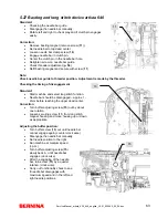
Page 58: ...on of front feed dog section Loosen screw 95 The pressure spring 96 causes the adjustment plate 97 to move up independently Position 1 0 mm gauge and press down Retighten screw 95 Important Check again after tightening the screw Correction of rear feed dog section Slightly loosen screws 98 Use a 5 5 mm open end wrench to turn the eccentric pin 99 until it reaches 0 9 mm level Tighten screws 98 Imp...

Page 59: ... that screw 77a points horizontally to the back visible through rear housing opening and lies against the circlip Retighten screw 77a carefully Fine adjustment What to adjust Loosen synchronizing disc screw 77a Pin balance piece loop lift position Turn synchronizing disc until light signal 3 turns off and light signal 4 turns on 27 5 Retighten screw 77a carefully 5 24 Basic balance setting Standar...

Page 60: ...gear drive against stop A and hold firmly while tightening screw 38 Use a screwdriver to slightly press crank shaft down at point B until toothed segment slides of mesh At the same time use a screwdriver to set the toothed segment parallel at point C and insert first tooth of toothed segment into first tooth of the drive gear D Check basic balance setting B 39 38 First tooth toothed segment parall...

Page 61: ...ter lever in the appropriate place Retighten screw 109 Checking correct position Place presser foot lifter lever up Set upper thread tension to 10 Model 640 manually rotate the top tension stepping motor cam counter clock wise to the highest setting When the lifter is actuated the presser foot lifter lever must drop Correcting the position Loosen screw 111 and turn adjustment eccenter 112 until th...

Page 62: ... thread tension stepping motor from minimum to maximum Set lifter lever 117 up and upper thread tension adjusting wheel artista 630 to position 10 The distance between the tension discs must be at least 0 3 mm Correction Raise presser foot lifter lever 117 Turn adjusting wheel to position 10 with artista 640 turn the cam of upper thread stepping motor to maximum Loosen lock nut 121 Adjust adjustin...

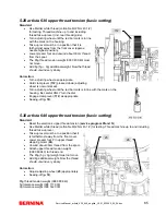
Page 63: ...eader Checking the timing of disengagement Standard Start machine and select long stitch function Needle bar should be disengaged approx 1 2mm before reaching the upper dead center Correction Turn buffer adjusting screw 15 out by about one rotation Loosen securing screw 11 from long stitch magnet housing and move housing up or down as appropriate Adjusting the buffer position Turn buffer screw 15 ...

Page 64: ...e spring screw as appropriate Note Turn screw counterclockwise to left to slacken Turn screw clockwise to right to tighten artista 640 RH hook lower thread tension basic setting Standard Use Mettler no 60 2 Nm 43 1 2 white thread Use no 006 543 70 01 gauge to adjust lower thread tension The bobbin case is inserted into the weight gauge in exactly the same way as into the hook Check Hold free end o...

Page 65: ...el is now unlocked Turn adjusting wheel until the red bar mark is in line with the mark on the housing Be careful ONLY turn the dial Engage clamp lever 112 as appropriate Sewing off p 18 5 30 artista 640 upper thread tension basic setting Standard Reset the electronic upper thread tension service program 5f and 5i Use Mettler white thread cotton Ne60 2 Nm 43 1 2 for testing Thread machine up to an...

Page 66: ... 15g Note Check if the gauge is set to zero calibrated Correction of tension Turn screw 113 to left or right to tighten or slacken tension Checking correct position The thread regulator spring 114 must lie on the limiter piece 115 There must be a distance of 1 6mm 0 3mm between spring and cover at the same time see drawing Correcting the position Slightly loosen securing screw 116 Adjust eccentric...

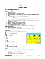
Page 67: ...is adjusted by turning the stitch width knob Brightness is adjusted by turning the stitch length knob Touch cross symbols on touch screen for calibration After calibration of touch screen the user sewing program can be directly accessed Exiting the test program Switch sewing embroidery computer off Wait about 20 seconds before switching sewing embroidery computer on again The s e computer can now ...

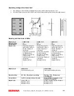
Page 68: ...Check the wiring for deformation tears or breaks Replace if necessary Check the connectors for deformations Replace if necessary Check L Print functioning Replace if necessary Replace S Print Check the wiring for deformation tears or breaks Replace if necessary Check the connectors for deformations Replace if necessary Check L Print functioning Replace if necessary Replace S Print What to test LED...

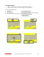
Page 69: ...ntering fields in the virtual keyboard The virtual keyboard data fields are 1 Data display field to completely delete press it 2 CLR field to individually delete press it 3 Data entering field letters numbers and symbols depending on display 4 How to select the data entering field modes a Capital letters and symbols b Low case letters and numbers c Special characters 1 d Special characters 2 1 2 3...

Page 70: ...urchchase Date Date of the purchase Time Power On Total number of operating hours powered Time Standby Total number of inactive operating hours powered Time Working Total number of active operating hours main shaft turning Time Embroidery Number of embroidering hours Time BSR Sewing time using BSR BERNINA Stitch Regulator Stitch Working Total number of stitches made Stitch Sewing Total number of s...

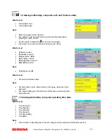
Page 71: ...en there What to test Software version Bootloader version Memory flash RAM EXP engine version BSR application version EMB BIOS version Note Updating see p 99 What to test Technical information data Note Technical data can be entered there in the page using the virtual keyboard The entered data gives the technician information on already made improvements 1c Sewing embroidery computer operating tim...

Page 72: ...dery computer servicing data What to test Lubricate Stitches Time for cleaning oiling appears at 180 000 stitches Reset Lubricate Stitches Resetting cleaning oiling time count Service Stitches Time for servicing appears at 2 000 000 stitches Reset Service Stitches Resetting servicing time count Cleaning interval The stitch counter up counter triggers a reminder at 180 000 stitches Clean and oil th...

Page 73: ...n a BERNINA USB memory stick Load the Customer Settings Loading of customer data to the sewing embroidery system Note Connect BERNINA USB memory stick and select required field Remove the stick after saving of data has been confirmed 1h Customer data What to test Customer First Name Customer s first name Customer Last Name Customer s last name Customer Telephone Number Customer s phone number Note...

Page 74: ...ch screen s calibration is misadjusted in such way that the function can no longer be selected in the service or setup program an alternative access is provided Alternative access If the touch screen is calibrated in such way that no selection can be made on the screen or the basic screen settings are misadjusted in such way that nothing can be seen anymore an alternative access is provided Access...

Page 75: ...lace if necessary Replace touch screen Replace S Print Note If a fault in the CFL light or the screens background lighting occurs then because of safety regulations the high voltage power is switched off If the screen is not lighting check the CFL first 2c Blank black LCD screen What to test Blank screen black to find any pixel errors Touch the touch screen at any place to return to menu 2 Repairi...

Page 76: ...s Data is displayed by the page with the page reference in green Explanations of data and how to change and save data are given below 3a Stitch width and stitch length adjusting knobs functions What to test The respective bar remains lit as long as the related adjusting knob is used Repairing note Check mechanical adjusting knob S Print connection If no signals occur replace the S Print 3b Functio...

Page 77: ...e bar display When using the heel kick function on the foot control symbol D 1 lights up Repairing note Check the foot control cable for deformation loose contacts tears or breaks Replace if necessary Check foot control ceramic plate and coal carrier functioning Replace if necessary Replace S Print 3e Threader sensor What to test As long as the threader is actuated the bar graph remains active Rep...

Page 78: ...and S Print cables for deformations tears or breaks Replace if necessary Check P Print functioning and replace if necessary Replace threader print and or S Print 3g Presser foot lifter micro switch What to test Raising the presser foot activates the micro switch and the bar display lights up in green Repairing note Check the cable for resistance deformations tears or breaks Replace if necessary Ch...

Page 79: ...ce deformations tears or breaks Replace if necessary Check connectors Replace lower thread indicator Replace S Print 3k Upper thread indicator What to test From below insert thread loop into thread tensioner up to the thread regulator spring Move thread regulator spring with thread loop up and down The bar display lights up in green if the sensor is active Repairing note Check settings of thread r...

Page 80: ...atic buttonhole foot no 3A Move slide back and forth Icon A or B lights up depending on the respective active signal Repairing note Check mechanical parts of buttonhole foot for ease of movement Replace if necessary Check buttonhole lens for dirt Clean or replace if necessary Check sensor for dirt Clean or replace if necessary Check the sensor connector for deformations Replace if necessary Check ...

Page 81: ...f necessary Replace P Print Replace S Print Note Press ESC Use the hand symbol to go to the next page That is where the interface tests are displayed 3n Mechanical fine adjusting of P Print What to test Balance piece in pinning position loop lift Select test 3n in service program Signal 3 just stopped to light Signal 4 starts to light What to adjust Rough adjusting of synchronizing disc p 58 Remov...

Page 82: ...le and press s icon to start the test Test successful appears if o k Test failed appears if an error occurred Repairing note Use Ohm meter to check EMB cable for resistance Replace EMB cable Replace embroidery module S Print Replace S Print 3t Foot control interface What to test Connect a foot control and press the t icon to start the test Test successful appears if o k Test failed appears if an e...

Page 83: ...th the page reference in green Explanations of tests and how to change and save tests are given below 4a Stitch length stepping motor What to test Press icon to start and stop test The stitch length stepping motor moves left to right and right to left and the feed dog moves forth and back Test done appears Test failed appears if an error occurred Press ESC to exit the test Repairing note If a step...

Page 84: ...ing motor What to test Press icon to start and stop test The upper thread tension stepping motor moves back and forth Test done appears Test failed appears if an error occurred Press ESC to exit the test Repairing note If a stepping motor does not spin the failure might be with the stepping motor or the S Print Swap the connections to find the defective PCB Attention Not when machine is powered Di...

Page 85: ...ot control and actuate Keep pressed until machine stops on own accord Test done appears Test failed appears if an error occurred Note Power in Watt is displayed in the left field The average value on CB machines a 630 is 41 Watts but mustn t be higher than 45 Watts The average value on RH machines a 640 is 38 Watts but mustn t be higher than 42 Watts The S P M adjustment factor is displayed in the...

Page 86: ... blue for a short period Set SSU slide control to right and actuate bar 2 The bar appears in blue for a moment If o k Test done appears If failed Test failed appears Press OK to confirm test Note Make sure that the SSU slide control is moved completely against the stop on the right and left position 4i Standard SSU speed What to test Press Start Stop button The motor r p m changes depending on the...

Page 87: ...inder motor What to test Press icon 4 to switch the winder motor on and off If o k Test done appears If failed Test failed appears Repairing note Replace winder motor Replace P Print Replace S Print 4l Basting magnet artista 640 What to test The basting magnet moves back and forth on pressing icon 4l Press icon 4l again to end the test If o k Test done appears If failed Test failed appears Repairi...

Page 88: ...con 4m Press icon 4m again to end the test If o k Test done appears If failed Test failed appears Repairing note Check the cable for deformation tears or breaks Replace if necessary Replace basting magnet Replace P Print Replace S Print 4n Thread cutting process artista 640 What to test Each pressing of the thread cutter button triggers the individual processes 10 working steps ...

Page 89: ...Thread tension activated Repairing note Check cutting edge of thread cutting blade If blunt replace thread cutting blade p 39 Check position of synchronizing disc see test 3n p 79 Replace P Print Replace S Print 6 7 Menu 5 Adjustments The tests are selected by pressing the appropriate button Testing and adjusting of balance buttonhole configuration presser foot pressure BSR foot thread tension Car...

Page 90: ...saving Repairing note Make sure that the basic mechanical settings are correct p 58 5b Mechanical balance fine adjusting What to test The number 9 pattern Thread machine place two layered sewing off cotton under the presser foot and start machine The 9 pattern must now be stitched in such way that the ends meet What to adjust Fine adjusting Turn balance shaft C in such way that the 9 is sewn corre...

Page 91: ... in such way that the 9 is sewn correctly i e stitching line ends meet exactly Picture 5 correct 5b Electronic balance fine adjusting What to test The leaf pattern Thread machine place two layered sewing off cotton under the presser foot and start machine The leaf pattern outline must be stitched in such way that the stitching line ends meet exactly The needle penetration points at the pattern beg...

Page 92: ... fine adjusting see test 5b in service program Check mechanical parts of automatic buttonhole foot smooth sliding of slide motion of signaller prism Replace automatic buttonhole foot Test sensors A and B in service program 3 Replace S Print and or buttonhole sensor PCB 5e Presser foot pressure sensor calibration end stops What to adjust Turn presser foot pressure adjusting wheel clockwise to minim...

Page 93: ...aving Repairing note The mechanical default value of the upper thread tension must be correctly set p 64 Note The advantage of the electronic upper thread tension lies in the fact that it can be adjusted without removing the covers 5g BERNINA Stitch Regulator BSR foot sewing program What to test BSR foot sewing off in customer s view What to adjust Attach and connect BSR foot Drop feed dog thread ...

Page 94: ...ronic upper thread tension default Do you really want to reset appears before final confirmation Press OK icon again to reset to default This brings you back to menu 5 5j Resetting to factory settings Reset All What to adjust Press OK icon to reset to factory settings Do you really want to reset appears before final confirmation Press OK icon again to reset to default This brings you back to menu ...

Page 95: ...ed EAN code Is entered by the production It can be changed using the virtual keyboard after replacing the EMB PCB EMB BIOS version Displays the installed BIOS version on the machine Repairing note EMB updating Use the right scrolling arrow to go to the purchase operating hours and stitching times data entry fields Purchase Date Date of sale purchase Time Power On Total hours under power Time Stand...

Page 96: ...stitch count in EMB Time Power On Total hours under power Time Standby Total hours under power but without activity Time Embroidery Stitching time in embroidery mode 6b Free arm adapter sensor What to test Attach free arm adapter and embroidery module Press icon b The bar appears in green after recognition of the sensor Test Successful appears Test failed appears if an error occurred Repairing not...

Page 97: ...ul appears Test failed appears if an error occurred Repairing note Replace EMB S Print 6d Y axis sensor What to test Attach embroidery module and hoop Press icon b The bar appears in green after recognition of the sensor Test Successful appears Test failed appears if an error occurred Note The type of the attached hoop is displayed after successful recognition Repairing note Replace Y sensor Repla...

Page 98: ...ping motor X moves back and forth Press icon f again to stop the test Test successful appears if o k Test failed appears if an error occurred Repairing note Check X drive belt tension Check if drive pinion of stepping motor X is free of threads Replace stepping motor X Replace EMB S Print 6g Movement of stepping motor Y What to test Attach embroidery module Press icon g The stepping motor Y moves ...

Page 99: ...ct adjust the center position Press OK to save the value and to return to menu 6 Press ESC to return to menu 6 without saving Repairing note Check tests 6c to 6g Check X and Y drive belt tension Check if drive pinion of stepping motors is free of threads 6i Embroidering using the test design What to test Hoop sew off cotton and stabilizer Attach embroidery module and hoop Select test design Stitch...

Page 100: ...be parallel to first diagonal row Y or X axis stiff driving slide or drive G Fill Stitch Stitch density Y direction must be even Y axis stiff driving slide or drive H Satin stitch The stitches must lie against each other Stiff driving caused by dirt in the drive probably thread remnants I Must match corner row Y or X axis stiff driving slide or drive J Must match corner row Y or X axis stiff drivi...

Page 101: ...o start the update 5 Update files are checked data and settings saved to the USB data stick and a reset triggered The update is carried out after resetting The sewing embroidery computer automatically starts with the new application in update mode 6 The settings and data that were saved on the USB data stick are sent back to the sewing embroidery computer The application changes to normal mode 7 T...

Page 102: ...ge Updating of new application failed Check data on USB data stick and try again Try alternative access p 103 Note In the event of error messages during updating see also user manual on pages 106 and 107 7 2 BSR update Service program 5h p 93 5h BSR foot update What to adjust Attach BSR foot Connect BERNINA USB data stick containing latest update file Press icon h to start updating process Follow ...

Page 103: ...ry computer off 3 Keep the needle positioning and pattern end keys pressed at the same time and switch sewing embroidery computer on 4 The application checks the update files on the USB data stick 5 Before proceeding you are asked whether the data is saved If yes start process by pressing the two needle positioning keys simultaneously If the machine data has not been saved yet stop the updating pr...

Page 104: ...Service Manual_artista_630_640_english_V4 01_032069_50_04 doc 104 8 Chapter Lubrication Plan 8 1 Lubrication Plan artista 630 ...

Page 105: ...Service Manual_artista_630_640_english_V4 01_032069_50_04 doc 105 8 2 Lubrication Plan artista 640 supplementary to artista 630 ...

Reviews: