background image

Tstat Series

- 1 -

Descriptions

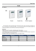
Tstat6


This full-featured CPU based thermostat is designed for small cooling and heating air handling sys-

tems in residential and commercial facilities.  The unit provides features which eclipse standard me-
chanical thermostats at a price that 

fi

 ts conventional HVAC projects.

Highlights:

-Tight control of 0.5°C provides comfortable indoor environment.
-High impact plastic enclosure provides durability in commercial environments.
-Customizable sequence of operation table (FCU with modulating or on/off valve,single or 3-speed fan, 
pressure independent VAV, stage sequencer)
-Available in Clock, Clock & Humidity, CO2 ,OCC and Zigbee options

Sales Price

Discount Price

OEM>50k/yr

Tstat6

39

37

36

Tstat6-CH

44

42

41

TSTAT6-CO2

90

75

60

TSTAT6-ZIGB

55

53

51

TSTAT6-OCC

41

39

38

Summary of Contents for Tstat Series

Page 1: ...projects Highlights Tight control of 0 5 C provides comfortable indoor environment High impact plastic enclosure provides durability in commercial environments Customizable sequence of operation table FCU with modulating or on off valve single or 3 speed fan pressure independent VAV stage sequencer Available in Clock Clock Humidity CO2 OCC and Zigbee options Sales Price Discount Price OEM 50k yr T...

Page 2: ...uencer An affordable CO2 sensing solution for HVAC DCV CO2 Performance Measurement Range 0 3 000 ppm display 2000ppm 5000ppm 10 000ppm are optional Accuracy 70 ppm or 5 of reading Repeatability 20 ppm Temperature Dependence Typ 0 2 of reading per C or 2 ppm per C whichever is greater referenced to 25 C 2 4 GHz IEEE 802 15 4 Compliant RF Transducer Programmable Output Power Up to 4 5dBm Tstat6 Zigb...

Page 3: ...ities use lighting control systems to control when the lighting fixtures are en ergized and thereby reduce the amount of power that is consumed to light these facilities Tstat6 OCC can be provided with an ambient light sensor and control input therefore The ambi ent light sensor and control input can be used to select a minimum level of light above which a lighting fixture is prevented from being ...

Page 4: ...to vari ous light sources IL using incandescent light IL using fluorescent light 1 2 typ Low supply voltage making device suitable for battery powered equipment VCC 2 7 V to 5 5 V Operating Temperature 30 C 85 C Maximum Ratings 25 C Characteristics Symbol Rating Unit Supply voltage VCC 0 5 to 7 V Output voltage VOUT VCC V Light current IL 5 mA Permissible power dissipation P 35 mW Operating temper...

Page 5: ...o 74 μ A Note 4 Light current measurement circuit Electrical and Optical Characteristics Ta 25 C Characteristics Symbol Test Condition Min Typ Max Unit Supply current ICC VCC 3 V EV 1000 lx RL 1 k Ω Note 2 620 μ A Light current 1 IL 1 VCC 3 V EV 1000 lx Note 2 Note 4 62 μ A Light current 2 IL 2 VCC 3 V EV 10 lx Note 3 Note 4 3 7 7 4 μ A Light current 3 IL 3 VCC 3 V EV 100 lx Note 3 Note 4 37 74 μ ...

Page 6: ...Tstat Series 6 ...

Page 7: ...Tstat Series 7 ...

Page 8: ...Tstat Series 8 Switching Time Measurement Circuit and Waveforms ...

Page 9: ...Tstat Series 9 Tstat6 Highlights ...

Page 10: ...Tstat Series 10 Tstat6 Jumper Settings Tstat6 Wiring Diagram ...

Page 11: ...Tstat Series 11 Tstat6 CO2 Highlights Tstat6 CO2 Jumper Settings ...

Page 12: ...Tstat Series 12 Tstat6 CO2 Wiring Diagram ...

Page 13: ...Tstat Series 13 Tstat6 Zigbee Highlights ...

Page 14: ...Tstat Series 14 Tstat6 Zigbee Jumper Settings Tstat6 Zigbee Wiring Diagram ...

Page 15: ...Tstat Series 15 Tstat6 OCC Highlights ...

Page 16: ...Tstat Series 16 Tstat6 OCC Jumper Settings Tstat6 OCC Wiring Diagram ...

Page 17: ... or decrease the set point value Waiting three seconds will confirm the setting When the current temp value is under the set point it will show the heating symbol When the current temp value is above the set point value it will show the cooling symbol 3 Now you are in the normal mode press both and at the same time and hold for several seconds It will switch into the menu mode Press or to scroll t...

Page 18: ...curate one so that all subsequent measurements are compared to the same benchmark The sensor inside the thermostat is a digital chip capable of resolving down to 0 06 C so the weak link in calibrating is usu ally the procedure used rather than the tstat accuracy Make sure the tstat is mounted in a location free of drafts tSS Temperature Sensor Select 0 3 0 The tstat has an extra input for use with...

Page 19: ...he operation to suit different variations of mechanical equipment Setting this value to a different value will cause the thermostat to stop working properly so be careful not to adjust this value unless you are familiar with the various sequences Standard Operation When SOP is set to 1 the sequence of operations is stored in a table that allows for basically any arbitrary sequence of operation for...

Page 20: ...es are in increments of 1 i e 10 means 10 and are in the same units C or F as the tstat Note The night heating setpoint is prevented through an internal software interlock from being set below 5 C regardless of the user heat ing setpoint and the value stored in NHS nSp APP Application 0 1 0 0 OFFICE applications mode The night time setpoints are specified value Night Heating Setpoint nHS value Nig...

Page 21: ...eating and cooling deadbands act in a way that reduces these settings by the amount of the deadband For example if the highest setpoint allowed is SHI 30 C and the heating deadband Hdb 2 C heating will actually only be active up to 28 C Similarly if the Cdb cooling deadband parameter is at 2 C and the minimum setpoint is at 20 C then cooling takes place only as low as 22 C LOC Keypad lockout 0 3 0...

Page 22: ...t Series 22 TSTAT6 CO2 calibration 1 Connect TSTAT6 CO2 to PC by RS485 2 Open T3000 and it show the following view 3 Click the button to scan the following view will appear and close it as the picture shows ...

Page 23: ... all the information of TSTAT6 5 Click button input it will show all the information of input same as output When you press input1 you can change the name according to your demand When you press range it will show a view of range there are different choices ...

Page 24: ...here is one list of Auto Manual when press manual the value can be set by the customer When you press auto it will change automatically according to the temperature and when you press cali bration you can adjust the value ...

Page 25: ...Tstat Series 25 6 When press the setting button it will show the parameter view When press PIDs Table it will open 3 PID view ...

Page 26: ...Tstat Series 26 ...

Page 27: ...ots Secure the wires the same way as you did for the power cables For the pressure switch we will need to determine the characteristics of the device and the pin layout Of the 3 pins we need to find the common pin which should be labelled on the datasheet For the PSN 30 300A this is pin 1 Using the multimeter to measure resistance between the common pin and another pin select the pin combination t...

Page 28: ... clear the Default Buildings list Exit this window The screenshot below highlights the the points of interest Following the key points of the diagram below press the Buildings button which is circled in red Under the cor responding columns change the Protocol to manual change COM Port to the correct port of your computer that corresponds with the connected Tstat6 and check that the Baud Rate is se...

Page 29: ...e Tool is located in the menu highlighted by a yellow circle in the screenshot below With referencing to the diagram above click on Network Points circled in red to get a general overview of what your Tstat6 unit is connected to If you want to change the units of temperature between celsius and fahrenheit click on the Configuration icon circled in black The parameter window will pop up and where t...

Page 30: ...roperly configure an output port to achieve a two stage heating and two stage cooling configuration with a single speed fan To set up the two stage heating and cooling navigate to the Configuration button circled in black in the picture located at the top of the next page and then select PIDs table circled red in the same picture to get to the desired window A PIDs Set Dialog window will display f...

Page 31: ...Tstat Series 31 ...

Page 32: ...ter used to show the status of firmware updates Writing 143 sets the config back to out of the box except for Modbus ID and baud rate Write 159 to fix the current config as the user defaults this is done automatically by T3000 any time a config file is loaded Writing 175 resets the unit back to the user defaults 16 MODBUS_UPDATE_STATUS Spare 17 MODBUS_UPDATE_PTR_HI Spare 18 MODBUS_UPDATE_PTR_LO Sp...

Page 33: ... RESERVED Blank for future use 56 RESERVED Blank for future use 57 RESERVED Blank for future use 58 RESERVED Blank for future use 59 RESERVED Blank for future use 60 RESERVED Blank for future use 61 RESERVED Blank for future use 62 RESERVED Blank for future use 63 RESERVED Blank for future use 64 RESERVED Blank for future use 65 RESERVED Blank for future use 66 RESERVED Blank for future use 67 RES...

Page 34: ...se 101 MODBUS_COOL_HEAT_MODE COOL_HEAT_MODE heating or cooling mode 0 none 1 cooling 2 heat ing 102 MODBUS_MODE_OPERATION MODE_OPERATION heating or cooling state 0 7 coasting cooling 1 2 3 heating 1 2 3 103 MODBUS_SEQUENCE SEQUENCE 0 internal test sequence outputs slowly cycle on off or ramp up down 1 normal operation according to the output tables 104 MODBUS_DEGC_OR_F DEGC_OR_F engineering units ...

Page 35: ...Unoccupied Override Timer Ort 0 disabled 0 number of minutes manual override is allowed 112 MODBUS_OVERRIDE_TIMER_LEFT OVERRIDE_TIMER_DOWN_COUNT Number of minutes remaining on the timer when unoccupied override timer is in effect 113 MODBUS_HEAT_COOL_CONFIG Heating cooling mode configuration HC 0 PID 1 Keypad 2 Digital_ in1 not used 3 Digital_in1 not used 4 Analog_in1 5 Analog_in2 114 MODBUS_TIMER...

Page 36: ... 137 MODBUS_ANALOG_INPUT7 Analog input7 value 138 MODBUS_ANALOG_INPUT8 Analog input8 value 139 MODBUS_EXTERNAL_SENSOR1 CO2 ppm optional 140 MODBUS_EXTERNAL_SENSOR2 Humidity optional 141 MODBUS_INPUT_MANU_ENABLE Auto Manual mode for inputs bit 0 input1 bit1 input2 and so on In manual mode you can write to the input registers 311 312 for debugging commissioning 142 MODBUS_FILTER Temperature sensor f...

Page 37: ...1 freeze protect sen sor input 2 occupancy sensor input 3 sweep off mode 4 clock mode 5 change over mode 172 MODBUS_ANALOG6_FUNCTION future Analog input6 function selection 0 normal 1 freeze protect sen sor input 2 occupancy sensor input 3 sweep off mode 4 clock mode 5 change over mode 173 MODBUS_ANALOG7_FUNCTION future Analog input7 function selection 0 normal 1 freeze protect sen sor input 2 occ...

Page 38: ...r heating 3 PWM 203 MODBUS_MODE_OUTPUT2 Determine the output2 mode 0 ON OFF mode 1 floating valve for cooling 2 floating valve for heating 3 PWM 204 MODBUS_MODE_OUTPUT3 Determine the output3 mode 0 ON OFF mode 1 floating valve for cooling 2 floating valve for heating 3 PWM 205 MODBUS_MODE_OUTPUT4 Determine the output4 mode 0 ON OFF mode 1 floating valve for cooling 2 floating valve for heating 3 P...

Page 39: ...N to OFF sec 229 MODBUS_OUTPUT3_DELAY_ON_TO_ OFF Output3 Relay3_delay_ON_TO_OFF delay time for output3 going from ON to OFF sec 230 MODBUS_OUTPUT4_DELAY_ON_TO_ OFF Output4 Relay4_delay_ON_TO_OFF delay time for output4 going from ON to OFF sec 231 MODBUS_OUTPUT5_DELAY_ON_TO_ OFF Output5 Relay5_delay_ON_TO_OFF delay time for output5 going from ON to OFF sec 232 MODBUS_OUTPUT6_DELAY_ON_TO_ OFF future...

Page 40: ...output4 Interlock for each output analog and digital output 0 inter lock always ON 1 DI1 determine the interlock status not used any more 2 AI1 determine the interlock status the range of AI1 must be ON OFF 3 AI2 determine the interlock status the range of AI2 must be ON OFF 4 TIMER OR the output OR with the period timer 5 TIMER AND the output AND with the period timer 249 MODBUS_INTERLOCK_OUTPUT5...

Page 41: ...l default 1 rotation old disabled feature 2 lighting control one key pad button can be assigned to toggle a relay on off 267 MODBUS_OUTPUT2_FUNCTION Output2 function setting see above 268 MODBUS_OUTPUT3_FUNCTION Output3 function setting see above 269 MODBUS_OUTPUT4_FUNCTION Output4 function setting see above 270 MODBUS_OUTPUT5_FUNCTION Output5 function setting see above 271 MODBUS_OUTPUT6_FUNCTION...

Page 42: ...AT1 293 MODBUS_FAN0_OPER_TABLE_ HEAT2 FAN0_OPERATION_TABLE_HEAT2 294 MODBUS_FAN0_OPER_TABLE_ HEAT3 FAN0_OPERATION_TABLE_HEAT3 295 MODBUS_FAN1_OPER_TABLE_ COAST FAN1_OPERATION_TABLE_COAST 296 MODBUS_FAN1_OPER_TABLE_ COOL1 FAN1_OPERATION_TABLE_COOL1 297 MODBUS_FAN1_OPER_TABLE_ COOL2 FAN1_OPERATION_TABLE_COOL2 298 MODBUS_FAN1_OPER_TABLE_ COOL3 FAN1_OPERATION_TABLE_COOL3 299 MODBUS_FAN1_OPER_TABLE_ HE...

Page 43: ...TABLE_COOL1 VALVE_OPER_TABLE_COOLING1 325 MODBUS_VALVE_OPER_TABLE_COOL2 VALVE_OPER_TABLE_COOLING2 326 MODBUS_VALVE_OPER_TABLE_COOL3 VALVE_OPER_TABLE_COOLING3 327 MODBUS_VALVE_OPER_TABLE_HEAT1 VALVE_OPER_TABLE_HEATING1 328 MODBUS_VALVE_OPER_TABLE_HEAT2 VALVE_OPER_TABLE_HEATING2 329 MODBUS_VALVE_OPER_TABLE_HEAT3 VALVE_OPER_TABLE_HEATING3 330 MODBUS_HEAT_UNIVERSAL_TABLE Number of Universal Heating St...

Page 44: ...tpoint 360 MODBUS_UNIVERSAL_DB_HI PID2 Heating Deadband TBD can write to either deadband or to setpoint 361 MODBUS_UNIVERSAL_DB_LO PID2 Cooling Deadband TBD can write to either deadband or to setpoint 362 MODBUS_ECOMONY_COOLING_SETPOINT Economy mode cooling setpoint 363 MODBUS_ECOMONY_HEATING_SETPOINT Economy mode heating setpoint 364 MODBUS_POWERUP_SETPOINT POWERUP_SETPOINT setpoint on power up 3...

Page 45: ...ow byte Lower 2 bytes of the PID1 units in ASCII 392 MODBUS_UNITS2_HIGH PID2 Units High byte Upper 2 bytes of the PID2 units in ASCII 393 MODBUS_UNITS2_LOW PID2 Units Low byte Lower 2 bytes of the PID2 units in ASCII 394 MODBUS_PID2_MODE_OPERATION PID2 heating or cooling state derived from PID2 register 240 0 coasting 1 cooling1 2 cooling2 3 cooling3 4 heating1 5 heating2 6 heating3 14 cooling4 15...

Page 46: ...y default 397 MODBUS_DISPLAY Spare 398 MODBUS_ICON ICON TABLE Set when certain icons are on off ICON1 TBD list the icons here one for Tstat6 and one for Ttsat7 TBD day icon night icon heating icon cooling icon fan icon 399 MODBUS_LAST_KEY_TIMER Last key pressed counter Minutes since the used last pressed a key 400 MODBUS_KEYPAD_VALUE Keypad encoded value Last keypress READ ONLY 401 MODBUS_DISPLAY_...

Page 47: ...ENT4_HI Weekend sleep time hour 433 MODBUS_DAY2_EVENT4_LO Weekend sleep time minute 434 MODBUS_LCD_TURN_OFF LCD turn off 0 turn off 1 normal 435 MODBUS_LINE1_CHAR1 User name line 1 characters 1 2 436 MODBUS_LINE1_CHAR2 User name line 1 characters 3 4 437 MODBUS_LINE1_CHAR3 User name line 1 characters 5 6 438 MODBUS_LINE1_CHAR4 User name line 1 characters 7 8 439 MODBUS_LINE2_CHAR1 User name line 2...

Page 48: ...user name line 1 characters 3 4 473 MODBUS_AI7_CHAR3 Input 7 user name line 1 characters 5 6 474 MODBUS_AI7_CHAR4 Input 7 user name line 1 characters 7 8 475 MODBUS_AI8_CHAR1 Input 8 user name line 1 characters 1 2 476 MODBUS_AI8_CHAR2 Input 8 user name line 1 characters 3 4 477 MODBUS_AI8_CHAR3 Input 8 user name line 1 characters 5 6 478 MODBUS_AI8_CHAR4 Input 8 user name line 1 characters 7 8 47...

Page 49: ...PIR sensor disable 630 1 PIR sensor real value 631 1 PIR sensor range 0 unocupied 1 occupied 632 1 PID2 VALVE TABLE COASTING 633 1 PID2 VALVE TABLE COOLING1 634 1 PID2 VALVE TABLE COOLING2 635 1 PID2 VALVE TABLE COOLING3 636 1 PID2 VALVE TABLE HEATING1 637 1 PID2 VALVE TABLE HEATING2 638 1 PID2 VALVE TABLE HEATING3 639 1 ID write protect 0 enable ID write 1 disable ID write ...

Page 50: ...tput 8 user name line 1 characters 7 8 511 MODBUS_SCHEDULEB_CHAR1 Schedule_B character 1 512 MODBUS_SCHEDULEB_CHAR2 Schedule_B character 2 513 MODBUS_SCHEDULEB_CHAR3 Schedule_B character 3 514 MODBUS_SCHEDULEB_CHAR4 Schedule_B character 4 515 MODBUS_SCHEDULEC_CHAR1 Schedule_C character 1 516 MODBUS_SCHEDULEC_CHAR2 Schedule_C character 2 517 MODBUS_SCHEDULEC_CHAR3 Schedule_C character 3 518 MODBUS_...

Page 51: ... calibration capacitance value future 559 MODBUS_HUMRH9_H Reserve for 9th calibration humidity value future 560 MODBUS_HUMCOUNT10_H Reserve for 10th calibration capacitance value future 561 MODBUS_HUMRH10_H Reserve for 10th calibration humidity value future 562 MODBUS_HUM_LOCK_A TBD humdity sensor factory calibration data write lockA only when A 12 and B 34 can write factory data 563 MODBUS_HUM_LO...

Page 52: ... item 588 MODBUS_DISP_ITEM_OUT5 Decide which item will be shown as the output item 589 MODBUS_DISP_ITEM_OUT6 Decide which item will be shown as the output item 590 MODBUS_DISP_ITEM_OUT7 Decide which item will be shown as the output item 591 MODBUS_OUTPUT_PWM_AUTO_ COAST PWM output range in COAST mode 0 CLOSE 1 OPEN 2 0 100 3 50 100 4 0 50 MSb 4 bits correspond to output4 and LSB 4 bits correspond ...

Page 53: ... 610 MODBUS_CO2_INPUT_MANUAL_ ENABLE CO2 sensor manual input enable 0 disble 1 enable 611 MODBUS_CO2_INPUT_VALUE CO2 sensor manual input value raneg 0 to 3000 612 MODBUS_CO2_CALIBRATION_ DATA CO2 sensor calibration data 613 MODBUS_UNIVERSAL_OFF_OUT PUT_BEGIN PID2 OFF TABLE COASTING 614 MODBUS_UNIVERSAL_OFF_OUT PUT_COOL1 PID2 OFF TABLE COOLING1 615 MODBUS_UNIVERSAL_OFF_OUT PUT_COOL2 PID2 OFF TABLE ...

Page 54: ..._WRITE_ENABLE ID write protect 0 enable ID write 1 disable ID write 640 MODBUS_COMMUNICATION_ CHECK_ENABLE 641 MODBUS_PIR_TIMER PIR TIMER 642 MODBUS_SUPPLY_SETPOINT VAV function supply setpoint 643 MODBUS_MAX_SUPPLY_SET POINT VAV function Maximum supply setpoint 644 MODBUS_MIN_SUPPLY_SET POINT VAV function Minimal supply setpoint 645 MODBUS_MAX_AIRFLOW_COOL ING VAV function Maximum airflow for coo...

Page 55: ...BUS_PID3_OUTPUT_COOL3 VAV function PID3_DIGITAL_OUTPUT_COOL3 669 MODBUS_PID3_OUTPUT_HEAT1 VAV function PID3_DIGITAL_OUTPUT_HEAT1 670 MODBUS_PID3_OUTPUT_HEAT2 VAV function PID3_DIGITAL_OUTPUT_HEAT2 671 MODBUS_PID3_OUTPUT_HEAT3 VAV function PID3_DIGITAL_OUTPUT_HEAT3 672 MODBUS_PID3_VALVE_OFF_TA BLE_BEGIN VAV function PID3_VALVE_OFF_TABLE_BEGIN 673 MODBUS_PID3_VALVE_OFF_TA BLE_COOL1 VAV function PID3...

Page 56: ...AT3 VAV function PID3_DIGITAL_OFF_OUTPUT_HEAT3 686 MODBUS_WIRELESS_PIR_RE SPONSE1 MODBUS_WIRELESS_PIR_RESPONSE1 687 MODBUS_WIRELESS_PIR_RE SPONSE2 MODBUS_WIRELESS_PIR_RESPONSE2 688 MODBUS_WIRELESS_PIR_RE SPONSE3 MODBUS_WIRELESS_PIR_RESPONSE3 689 MODBUS_WIRELESS_PIR_RE SPONSE4 MODBUS_WIRELESS_PIR_RESPONSE4 690 MODBUS_WIRELESS_PIR_RE SPONSE5 MODBUS_WIRELESS_PIR_RESPONSE5 ...

Reviews: