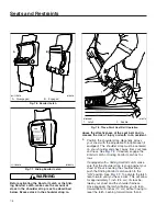
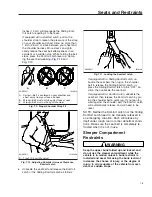
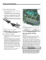
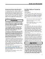
background image

On vehicles without Optimized Idle, accessory heat-
ers function when the ignition switch is in the OFF
position and the cab load disconnect switch (if
equipped) is in the ON position.

On vehicles with Optimized Idle, accessory heaters
function when the ignition switch is in the ON or ACC
position, the cab load disconnect switch (if equipped)
is in the ON position, and the parking brake is en-
gaged. The heater may run briefly after the ignition
key has been turned to the OFF position.

IMPORTANT: Wait eight minutes after shutting
down an accessory heater before turning the
cab load disconnect switch (CLDS) to OFF.

NOTE: The low voltage disconnect (LVD) control
prevents a heater from draining the batteries
below starting voltage.

Eberspaecher (Espar) Heater

Refer to the Eberspaecher website,

www.eberspaecher-na.com

for additional informa-

tion.

Eberspaecher Digi-Max D1000 Controller

To turn the heater on, press the POWER button. See

Fig. 6.6

The display will indicate that heater is en-

abled and show the remaining runtime and the set
temperature. See

Fig. 6.7

The green LED indicates

that the heater is on.

To adjust the desired temperature, press the left or
right arrow buttons. The left arrow button lowers the
desired temperature, and the right arrow button
raises it. The adjustment range is from 48 to 93°F (8
to 34°C).

To turn the heater off, press the POWER button
again. The heater will initiate a 5- to 8-minute cooling
cycle.

The controller has a real-time diagnostic feature, and
will automatically display fault codes as they happen
(e.g. 48—Check Fuel Pump). The red LED will illumi-
nate, indicating that maintenance is required.

The controller has a programmable run timer that will
display a maintenance message on the LCD after the
set time limit when the heater is off. See

Fig. 6.8

.

The fault codes and maintenance messages will not
prevent the heater from operating, but they reflect
conditions that should be addressed promptly.

Webasto Heater

Webasto heaters have a heat mode and a vent
mode. The fan speed is adjustable in the vent mode.
The control also has a timer function, allowing a start
time and/or duration to be set.

To turn the heater on, push the ON/OFF button. See

Fig. 6.9

The LCD screen displays the mode, ambi-

ent temperature, set temperature, timer, and fan
speed. See

Fig. 6.10

.

Refer to the Webasto website,

techwebasto.com

,

for additional information.

f611463

10/17/2016

1

2

3

4

5

6

1.

Heater Enabled LED (green)

2.

LCD Display

3.

Maintenance Required LED (red)

4.

Temperature UP Button (right arrow)

5.

Power Button

6.

Temperature DOWN Button (left arrow)

Fig. 6.6, Eberspaecher Digi-Max D1000 Controller

f611462

10/17/2016

1

2

1.

Remaining Runtime

2.

Set Temperature

Fig. 6.7, Controller LCD

f611464

10/17/2016

Fig. 6.8, Maintenance Required Message

Climate Controls

6.4

Summary of Contents for NEW CASCADIA 2016

Page 1: ... NEW CASCADIA Driver s Manual Part Number STI 500 Publication Number STI 500 8 ...

Page 2: ...itting a road obstacle that will assist in understanding how a vehicle s systems performed The EDR is designed to record data re lated to vehicle dynamics and safety systems for ap proximately 60 seconds This data can help provide a better understanding of the circumstances in which crashes and injuries occur Data recorded includes the following items how various systems in the vehicle were oper a...

Page 3: ...t may order a recall and remedy campaign However NHTSA cannot become involved in individual problems between you your dealer or Daimler Trucks North America LLC To contact NHTSA you may call the Vehicle Safety Hotline toll free at 1 888 327 4236 TTY 1 800 424 9153 go to www safercar gov or write to Administrator NHTSA 1200 New Jersey Avenue SE Washington DC 20590 You can also obtain other informat...

Page 4: ...per Features 8 1 9 Electrical System 9 1 10 Engine Starting Operation and Shutdown 10 1 11 Optional Engine Systems 11 1 12 Emissions and Fuel Efficiency 12 1 13 Brake Systems 13 1 14 Steering System 14 1 15 Automated and Automatic Transmissions 15 1 16 Manual Transmissions and Clutch 16 1 17 Drive Axles 17 1 18 Fifth Wheels 18 1 19 Trailer Couplings 19 1 20 Headlight Aiming 20 1 21 Vehicle Appeara...

Page 5: ......

Page 6: ...tification Component Information Label 1 1 Component GWR Label 1 1 Federal Motor Vehicle Safety Standard Labels 1 1 Canadian Motor Vehicle Safety Standard Labels 1 1 Emissions Labels 1 1 Customer Assistance Label 1 4 ...

Page 7: ...s with fifth wheels are marked as certified by means of the Canadian National Safety Mark printed on the vehicle certification label which is attached to the driver side door frame B pillar See Fig 1 5 Trucks built without a cargo body and tractors built without a fifth wheel that are intended for service in Canada have an incomplete vehicle certification label attached to the driver side B pillar...

Page 8: ...MUM GWR BY COMPONENT KG LBS COMPONENT AXLES SUSPENSION TIRES RIMS HUBS SPOKES BRAKES STEERING FRONT AXLE 2ND INT AXLE 3RD INT AXLE 4TH INT AXLE 5TH INT AXLE 6TH INT AXLE REAR AXLE COMPONENT GVWR 5443 12000 9072 20000 9072 20000 CHASSIS ENG TRANS 5TH WHEEL PARK BRAKE AXLE VIN 1FUJGBDV4GLZZ9999 1ST INT AXLE 5443 12000 5601 12350 6713 14800 6032 13300 6032 13300 6032 13300 9072 20000 9253 20400 11612...

Page 9: ...tions 40 CFR Part 205 and label it for compliance Vehicle Emission Control Information Label Model year 2013 and later vehicles meet additional requirements as specified by federal greenhouse gas and fuel efficiency regulations GHG14 Model year 2017 and later vehicles meet similar requirements as f080199 06 22 2016 DAIMLER TRUCKS N A LLC 07 15 52 000 23 587 110 120 120 S S S MANUFACTURED BY DATE O...

Page 10: ... with the VIN read able by dealer apps to bring up information about the vehicle The customer assistance label is located on the driver side B pillar as shown in Fig 1 2 f080201a 10 17 2016 VEHICLE NOISE EMISSION CONTROL INFORMATION DAIMLER TRUCKS NORTH AMERICA LLC DATE OF MANUFACTURE 01 16 THIS INCOMPLETE VEHICLE AS DELIVERED BY DAIMLER TRUCKS NORTH AMERICA LLC CONFORMS TO U S EPA REGULATIONS FOR...

Page 11: ......

Page 12: ...2 Vehicle Access Door Locks and Handles 2 1 Grab Handles and Access Steps 2 1 Cab to Sleeper Access 2 3 Sleeper Door 2 3 Sleeper Luggage Door 2 3 Back of Cab Access 2 3 Hood Opening and Closing 2 5 ...

Page 13: ...on the door lever This will unlatch the door whether or not it is locked To unlock the door without unlatching it pull the lock button upwards Grab Handles and Access Steps CAUTION Slipping or falling from the vehicle can result in personal injury or property damage Wet or dirty shoes greatly increase the chance of slipping or falling If your shoes are wet or dirty be especially careful when enter...

Page 14: ...tempt to exit with your back to the cab as you would going down a flight of stairs It is easier to slip or lose your balance If you slip when exiting in this way there is a greater likelihood of per sonal injury 1 Grasp the steering wheel with your right hand and the A pillar grab handle with your left hand and place your left foot on the top step See Fig 2 3 2 Face into the cab and grasp the B pi...

Page 15: ... access on vehicles with velour sleeper curtains unfasten the snaps at one side then push the curtain to the opposite side Sleeper Door The sleeper door Fig 2 5 Ref 1 is not intended for entry or exit The door is intended only as a con venient means to stow or remove personal belong ings in and from the sleeper area To open the sleeper door from the inside push down on the lever handle located ins...

Page 16: ... around and always face in to ward the deck plate when climbing up or down Wet or dirty shoes steps or grab rails greatly increase the chance of slipping or falling If your shoes or the contact areas are wet or dirty clean and dry them as much as possible before ac cessing the back of cab area and be especially careful when climbing or standing on the vehicle Never jump onto or off of a vehicle do...

Page 17: ...e grab handle 4 Move one foot to the bottom step 5 Step to the ground with your upper foot first Hood Opening and Closing The hood can be raised to a full open position Tilt assist struts help you to raise the hood and to lower it to the operating position In the operating position the hood is secured to the cab mounted cowl by a hold down latch on each side Opening the Hood 1 Release both hood ho...

Page 18: ...3 Instruments Instrumentation Control Unit 3 1 Warnings Indicators and Messages 3 2 Instruments 3 7 Driver Display 3 12 ...

Page 19: ... Messages Instruments Driver Display Ignition Sequence When the ignition is turned on the ICU runs a self check Observing the ignition sequence is a good way to ensure the ICU is functioning properly IMPORTANT Do not crank the engine until the ICU self check is complete NOTE Air gauges do not complete a sweep of their dials during the ignition sequence When the ignition is turned on the following ...

Page 20: ... 1 7 C optional Warnings Indicators and Messages Warning and indicator lights telltales with icon sym bols are displayed on the ICUC The positions of the lights may vary but the telltales are standard for all applications Soft telltales are shown on the driver display See Table 3 1 for a listing of standard and commonly used warnings indicators and messages Telltales illuminate in red warning ambe...

Page 21: ...ly bring the vehicle to a stop as soon as possible N A PARK P Red Parking Brake EPA10 and Newer Indicates the parking brake is engaged N A Red Unfastened Seat Belt Activates with an audible alert when the system detects that the parking brake is off and the driver seat belt is not fastened on some vehicles On other vehicles this lamp illuminates for 15 seconds when the ignition is first turned on ...

Page 22: ... that a parked regen is required immediately An engine derate and shutdown will occur N A Amber Malfunction Indicator Lamp MIL Indicates an emissions related fault See the engine operation manual for details N A Amber Vehicle ABS Momentary illumination indicates the vehicle ABS is engaged Solid illumination indicates a problem with the vehicle ABS Repair the ABS immediately to ensure full braking ...

Page 23: ... Active Brake Assist GHG14 and newer Indicates the Active Brake Assist system is not available 04 22 2016 f611353 Amber Lane Departure Warning Indicates that lane departure warning is disabled due to minimum speed no lane markings or system not available NOTE Only on vehicles equipped with Detroit Assurance radar 06 28 2016 f611372 Green Optimized Idle Indicates optimized idle is enabled N A Green...

Page 24: ...able limit determined by the gross axle weight rating GAWR Load transfer mode will automatically deactivate when the vehicle reaches 45 mph 72kmh 11 09 2016 f611472 N A Start Blocked Indicates that the system is preventing the starter from cranking This can occur when the ignition switch is turned to START before the gauge sweep has completed NOTE Display of the Start Blocked screen does not indic...

Page 25: ...ndition does not improve Bring the vehicle to a stop on the side of the road before the engine shuts down Some vehicles may have a shutdown override switch which may be used to momentarily override the shutdown sequence See Chapter 10 for detailed information regarding the shutdown process IMPORTANT Do not attempt to restart the en gine while the vehicle is moving Bring the ve hicle to a safe stop...

Page 26: ...or Detroit engines if coolant temperature rises above the maximum temperature listed in Table 3 3 the CHECK engine lamp will illuminate If the condi tion does not improve the STOP engine lamp will also illuminate and an audible warning will sound The engine will then derate or shut down depending on the type of engine protection system installed Maximum Coolant Temperature Engine Make Temperature ...

Page 27: ...ew to create a guide for checking engine condition Table 3 4 Minimum Engine Oil Pressure Engine Oil Temperature Gauge NOTICE A sudden increase in oil temperature that is not caused by a load increase may indicate mechani cal failure Bring the vehicle to a safe stop and investigate the cause to prevent further damage Do not operate the engine until the cause has been determined and corrected During...

Page 28: ...lable The U S version of the speedometer Fig 3 1 item 1 regis ters speed in both miles per hour mph and kilome ters per hour km h with mph in larger numbers The metric version of the speedometer face reverses this arrangement with km h in larger numbers Suspension Air Pressure Gauge A suspension air pressure gauge Fig 3 8 registers the air pressure applied to the vehicle air suspension Tachometer ...

Page 29: ... potential bat tery charging problems and have them fixed before the batteries discharge enough to create starting diffi culties A digital voltage display is integrated in the driver display The voltmeter will normally show approximately 13 7 to 14 1 volts when the engine is running The voltage of a fully charged battery is 12 7 to 12 8 volts when the engine is off Battery voltage under 12 0 volts...

Page 30: ...gory See Fig 3 13 For Quick Access Systems menus if available press the Quick Access System Settings button in the right hand switch pod If Quick Access Systems menus are not available the button will take the user to the home screen The top level menu categories Fig 3 14 are Basic Information Drive Time Systems Vehicle Operations Maintenance Infotainment User Settings Quick Access Systems if avai...

Page 31: ...ssion and axle oil temperatures 2 customizable gauge information continued 3 diesel particulate filter DPF status 4 tire pressure monitoring system TPMS set tings and sensor learning see Fig 3 18 individual axle tire pressure and temperature monitoring 5 differential locks 6 list of vehicle settings and shortcut to Quick Ac cess Systems screens Maintenance Screens The maintenance screens are used ...

Page 32: ... AUX 2 telephone showing signal strength battery level phone number and active call length User Settings Screens User settings screens allows the driver to manage ICU parameters See Fig 3 21 Use the Menu Up and Menu Down to navigate the user settings screens 1 user settings dash lighting f611355 06 29 2016 1 2 3 4 5 6 8 7 NOTE Navigate the top level menu categories using the Menu Right and Menu Le...

Page 33: ...d gauges key alert language 2 alarm clock status and settings f611356 06 20 2016 3 1 2 1 Home Screen 2 Trip Report 3 Trip Leg Report Fig 3 15 Basic Information Screens f611357 06 20 2016 3 1 2 4 1 Current Vehicle Speed 2 Driver Assistance Systems 3 Eco Driver Feedback 4 Camera Fig 3 16 Drive Time Systems Screens Instruments 3 15 ...

Page 34: ...e lowest Warning red Caution yellow Notice blue Warnings alert the driver to situations or conditions that may pose a threat to control of the vehicle Fol low all instructions given in the message Cautions alert the driver to situations or conditions that may result in damage to vehicle components or derating of engine power Notices alert the driver to situations or conditions that may improve fue...

Page 35: ...359 06 20 2016 3 1 2 1 Notices Cautions and Warnings 2 Diagnostics 3 Engine Maintenance Fig 3 19 Maintenance Screens f611360 06 20 2016 2 1 1 Audio 2 Telephone Fig 3 20 Infotainment Screens Instruments 3 17 ...

Page 36: ...f the settings screens Use the Menu Up and Menu Down buttons to navigate between the settings 1 Settings Main Screen 2 Select Settings 3 Dash Brightness 4 Courtesy and Entrance Lighting 5 Units 6 Time 7 Customized Gauges 8 Key Alert 9 Language 10 Alarm Clock Fig 3 21 User Settings and Alarm Clock Screens Instruments 3 18 ...

Page 37: ...5 and 6 are unavailable while the vehicle is in motion 1 Cruise Control Settings 2 Transmission Settings eCoast and Creep Mode 3 Attention Assist 4 Idle Adjust 5 Power Take Off 6 Optimized Idle Fig 3 22 Quick Access Systems Screens Instruments 3 19 ...

Page 38: ...f611444 10 31 2016 Fig 3 23 Sample Alert Messages Instruments 3 20 ...

Page 39: ......

Page 40: ... 4 6 Powertrain Controls 4 7 Cruise Control 4 9 Dash Mounted Brake Controls 4 13 Windshield Wiper and Washer Controls 4 14 Suspension Controls 4 15 Fifth Wheel Controls 4 17 Adjustable Steering Column Controls 4 18 Radio Controls 4 18 Climate Controls 4 19 Seat Controls 4 20 ...

Page 41: ...radio stereo system heater and A C fan mirror defog windshield fan ether start system air dryer backup lights Turn the key clockwise past the OFF position to reach the ON position With the switch in the ON po sition all electrical systems become operable and the warning and indicator lamps illuminate Wait for three seconds before starting the engine IMPORTANT Do not crank the engine until the ICU ...

Page 42: ...This is a momentary switch that en ables the driver to deactivate the DRL Press the upper half of the switch briefly to activate or deacti vate the DRL Fog Lights Fog lights are designed to reduce glare in foggy con ditions The low beam headlights must be on in order to turn the fog lights on Pull the headlight switch out ward to activate the fog lights Hazard Warning Lights The hazard warning lig...

Page 43: ...tically turns on the headlights if the windshield wipers are on and the vehicle is moving faster than 10 mph 16 km h At speeds between 10 and 40 mph 16 to 64 km h cycling the headlight switch will turn the head lights off High Beam Headlights With the low beam headlights on push the turn signal lever away from you to turn on the high beam headlights See Fig 4 5 To turn off the high beam headlights...

Page 44: ...nal lever the lever auto matically returns to the neutral position when the steering wheel returns to the straight ahead position after a turn Utility Lights Utility lights can be swivel mounted on upper half of the cab mounted on the exhaust support or flush mounted on the back of the cab or sleeper Press the upper half of the switch to turn the utility lights on or off When activated a red indic...

Page 45: ... located on the un derside of the lower bunk on both sides Both lights turn on when either baggage compartment door is opened to illuminate the baggage compartment The lights also come on when the lower bunk is raised f602577 04 18 2016 1 2 3 4 5 6 7 8 9 10 1 Foot Well Lights 2 Door Entry Courtesy Lights 3 Sleeper Floor Lights 4 Baggage Compartment Lights 5 Sleeper Work Light 6 Sleeper Reading Lam...

Page 46: ...is located on the headliner between the bunk and the cab on sleeper vehicles The rear cab dome light will activate with the dome lights when a door is opened then stay on for a short time after both doors are closed Use the dash mounted switch or the switch in the sleeper panel to activate the rear cab dome light See Fig 4 2 Sleeper Dome Light The sleeper dome light has both direct and ambient lig...

Page 47: ...r each driver controlled differential lock DCDL See Fig 4 11 For more information about differential locks and using them for traction control see Chapter 17 Engine Brake Switches NOTE See Chapter 13 for detailed information about engine brake operation Whenever vehicle braking is required on good road conditions the engine brake may be used in con junction with the service brakes There is no time...

Page 48: ...e to prevent the vehicle from rolling while on steep grades and to allow for a controlled launch HSA delays the release of the service brakes until enough torque is available to begin moving the vehicle forward for a maximum of 3 seconds HSA is on by default It can be turned off by pressing and releasing the HSA override switch on the dash see Fig 4 14 Power Take Off PTO Switch To activate the PTO...

Page 49: ...ing a con stant speed such as in heavy traffic or on roads that are winding icy snow covered slippery or roads with a loose driving surface Failure to fol low this precaution could cause a collision or loss of vehicle control possibly resulting in per sonal injury or property damage NOTICE When the cruise control is engaged do not at tempt to shift gears without using the clutch pedal Failure to f...

Page 50: ...nts Detroit Diesel engines only Single press increases cruise speed by 1 mph If no previous set speed is stored pressing the but ton sets the cruise speed 1 To cruise at a particular speed 1 1 Depress the accelerator pedal until the speedometer reaches the desired speed NOTE Cruise control is cancelled if the brake or clutch pedal is depressed or ve hicle speed drops below the minimum cruise contr...

Page 51: ...is exceeded the driver display shows the status and time remaining until the vehicle decelerates See Fig 4 19 Intelligent Powertrain Management IPM IPM is an optional fuel savings application that func tions as a predictive cruise control Using 3D digital map technology and GPS IPM evaluates the upcom ing road grade about a mile in advance to determine the best use case for most fuel efficient veh...

Page 52: ... whenever possible Driver interaction with IPM is the same as conventional cruise control using the standard cruise control buttons In the event of a problem with IPM or when driving on a road with no profile information available the system reverts to conventional cruise control Using the throttle pedal will abort the current IPM use case Disengaging the cruise control will also disen gage IPM De...

Page 53: ...can be released the air pressure in either air brake system must be at least 65 psi 447 kPa If the trailer is not equipped with spring parking brakes pull the parking brake valve out to apply the tractor parking brakes and the trailer service brakes Trailer Air Supply Valve The red octagonal shaped knob operates the trailer air supply valve which charges the trailer air supply system and releases ...

Page 54: ...control and a reduced braking distance The ABS is designed to communicate with a trailer ABS if they are compatible Compatibility will result in the illumination of the trailer ABS lamp during ve hicle start up and fault detection The trailer ABS lamp will not illuminate unless a compatible trailer is connected to the tractor Vehicles with ABS may have Automatic Traction Con trol ATC On these vehi...

Page 55: ... 64 km h cycling the headlight switch will turn the headlights off The windshield washer button is located at the end of the turn signal lever Momentarily press the wind shield washer button to initiate a single wipe without activating the washer pump The wipers will swipe one full cycle and return to the inactive position To operate the windshield washers press and hold the button in After a shor...

Page 56: ... load transfer mode is active Load Transfer will display in the message field of the driver display See Figure 4 29 Suspension Height If the suspension is at normal height each up press increases the suspension height an increment unless the suspension is at maximum height a down press lowers the suspension to its low est set point usually axle stops If the suspension is below normal height an up ...

Page 57: ...e STOP key on the re mote for 2 seconds Confirm the deactivation of standby mode by attempting to turn the remote on and adjust the suspension which should not be pos sible ECAS Remote Control Keys and Functions f611211 02 03 2017 Key Function Remote Control On Off The middle light will remain lit while the remote is active Memory keys Pressing the STOP key and a memory key simultaneously will sto...

Page 58: ...the switch to turn trailer auxiliary function off See Fig 4 32 Adjustable Steering Column Controls To unlock the steering column to adjust it pull the steering column locking lever out and away from the column See Fig 4 33 With the column unlocked the steering wheel can be adjusted up and down and tilted fore and aft Once the wheel is in the desired position lock the position by pushing the lever ...

Page 59: ...re Turn the switch clockwise to the red area for warm air Turn the switch counterclock wise to the blue area for cool air The A C cools and dehumidifies the air inside the cab Press the A C button located in the center of the temperature control switch to turn the A C on and off The mode control switch allows the control of air flow through the face outlets the floor outlets the defrost windshield...

Page 60: ...is adjustment enables the back rest to pivot forward or backward 2 Lumbar Support Lumbar support changes the shape of the seat back to give more or less sup port to the occupant s lumbar lower back area This adjustment is either mechanical or air con trolled depending on make and model of the seat 3 Isolator This feature reduces the amount of road shock by isolating the occupant from the motion of...

Page 61: ...Tilt 2 Lumbar Support 3 Isolator Feature 4 Height Adjustment 5 Bottom Cushion Angle fore and aft cushion height 6 Fore and Aft Seat Slide seat track adjustment 7 Seat Tilt 8 Headrest Adjustment Fig 4 37 General Seat Adjustments Driver Controls 4 21 ...

Page 62: ...5 Driver Assistance Features Detroit Assurance Radar 5 1 OnGuard Collision Safety System 5 7 Lane Departure Warning LDW 5 10 Enhanced Stability Control ESC 5 12 Zonar 2020 Tablet 5 13 ...

Page 63: ...sate for any driver impairment such as drugs alcohol or fatigue Failure to drive safely and use the system prop erly could result in personal injury and or death and severe property damage Safety Information Adaptive cruise control ACC may not detect narrow vehicles driving in front like motorcycles or vehicles driving in a different lane In particular be aware of the following situations cornerin...

Page 64: ... if the vehicle is traveling slower than 10 mph 15 km h the transmission is in neutral for more than 5 seconds reverse gear is selected ABS is deactivated there is a malfunction in the brake system or the electronic management system or the distance sensor initialization is not yet com plete f611352a 09 28 2016 11 15 9 12 16 10 14 13 8 7 1 2 3 4 6 5 1 Cruise Accelerate Resume 2 Quick Access System...

Page 65: ...n front if necessary Overtaking NOTE It is possible to exceed the set speed when overtaking The set speed can be exceeded using the accelera tor pedal When the accelerator pedal is released the set speed will be resumed Deactivating the System Press the CNCL switch or press the brake pedal to deactivate cruise control NOTE The speed remains stored when ACC is deactivated Tail Gate Warning Tail Gat...

Page 66: ...e edge of the lane ABA may not detect narrow vehicles driving in front like motorcycles or vehicles driving on a different line ABA does not automatically adapt to road and traffic conditions Brake the vehicle using the service brake if an event window with the Warning symbol ap pears on the driver display screen an intermittent warning tone sounds or an intermittent warning tone sounds and auto m...

Page 67: ...5 seconds to pre vent it from rolling away If an emergency braking maneuver has been performed remove the ve hicle from the area of danger as soon as possible while paying attention to the traffic situation Stop the engine and apply the parking brake to prevent the vehicle from rolling away Make sure that the vehicle is in proper operating order and that the load is secured properly The driver can...

Page 68: ... is limited ABA and ACC may unexpectedly issue warnings or brake your vehicle Overtaking 12 18 2014 f040838a When passing ABA and ACC may unexpectedly issue warnings or brake your vehicle if the vehicle is too close to the vehicle in front and is in the same lane Winding stretches of road 12 18 2014 f040844a On winding stretches of road ABA and ACC cannot detect which lane the vehicle in front is ...

Page 69: ...n alert and conscientious professional driver It is not intended to be relied upon to operate a vehicle Use the system in conjunction with rearview mir rors and other instruments to safely operate the vehicle Operate a vehicle equipped with the On Guard in the same safe manner as if the CWS were not present The OnGuard Collision Safety System is not a substitute for safe normal driving procedures ...

Page 70: ...Screen Color Description Amber Data Error Table 5 3 OnGuard Display Screen Background Colors IMPORTANT CMS and active braking are not operational at vehicle speeds below 15 mph 25 km h The CWS cannot be disengaged or turned off and is always active at vehicle speeds above 15 mph 25 km h Standby When no lead vehicle is detected the display shows that the CMS is on and the radar is searching See Fig...

Page 71: ...y background will turn yellow The alert will end when vehicle speed drops below the lead vehicle s speed and the following distance is increased NOTE The following distance alert does not operate at speeds below 15 mph 25 km h Collision Warning If the lead vehicle is traveling slower than the driver s vehicle the CMS warns of an impending collision by emitting an urgent audible alert and displayin...

Page 72: ...omponent operation and acts as a valuable OnGuard system diagnostic tool The header will dis play either COMPONENT TEST or ACC FUNCTION depending on the software release version of the On Guard system The component test screen shown in Fig 5 15 provides access to the following compo nents press the up or down arrows to scroll through the menu brake pedal position EBS brake switch CCVS brake switch...

Page 73: ...hield When lane departure warning is activated and it detects lane markings on the road surface it warns the driver that they may be leaving the lane unintentionally Lane departure warning issues warnings if the speed is above approximately 37 mph 60 km h When driving over lane markings unintentionally the volume of audio equipment like the radio and or hands free systems is reduced and a directio...

Page 74: ...sk detection a dash warning light illuminates and an audible tone sounds The purpose is to advise the driver that the previous ma neuver produced a rollover risk The roll stability control system within ESC auto matically reduces engine power applies the engine brake and or applies the tractor and trailer brakes when the acceleration sensor detects that the vehicle is at risk of rolling over ESC a...

Page 75: ... the roll stability control system intervenes Zonar 2020 Tablet The Zonar 2020 on board tablet is an optional fea ture that tracks hours of service posts driver alerts documents pre and post trip vehicle inspections and provides advanced navigation See Fig 5 19 The tablet operates in conjunction with the connectiv ity onboard platform to provide communication be tween drivers and fleet managers Re...

Page 76: ...6 Climate Controls Cab Climate Controls 6 1 Sleeper Climate Control Panel 6 2 Accessory Heaters 6 3 ...

Page 77: ...usty or smoky air from entering the cab See Fig 6 2 Recirculation mode can also decrease the time required to cool or heat the cab interior dur ing extreme outside temperature conditions An amber indicator on the recirculation button will illumi nate when the recirculation mode is activated The recirculation button will not work when the mode control switch is in either defog or defrost modes NOTE...

Page 78: ...ab See Fig 6 4 Press the bunk override button to copy the current cab HVAC temperature and fan settings to the sleeper HVAC An amber indicator will illuminate when bunk override mode is activated Subsequent changes to the cab HVAC setting will be sent to the sleeper HVAC until the bunk override button is pressed again to cancel the bunk override mode Ad justing the sleeper climate controls at any ...

Page 79: ...oning button located in the center of the temperature control switch to turn the A C on and off Smartway Certified Parked Heater Operation All vehicles equipped with diesel operated coolant heaters are Smartway Certified The coolant heater will keep the engine coolant between approximately 150 and 180 F 65 and 82 C Heated coolant is routed through the auxiliary HVAC heater core to allow heater onl...

Page 80: ...range is from 48 to 93 F 8 to 34 C To turn the heater off press the POWER button again The heater will initiate a 5 to 8 minute cooling cycle The controller has a real time diagnostic feature and will automatically display fault codes as they happen e g 48 Check Fuel Pump The red LED will illumi nate indicating that maintenance is required The controller has a programmable run timer that will disp...

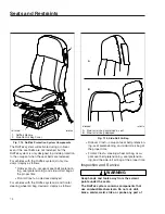
Page 81: ...ion button Select Edit from the sub menu 4 Using the rotary knob select the day To confirm press the selection button 5 Using the rotary knob select the start time To confirm press the selection button 6 Using the rotary knob select the run time To confirm press the selection button f611465 10 21 2016 1 2 3 3 4 1 Rotary Knob 2 ON OFF Button 3 Indicator Light 4 Selection Button Fig 6 9 Webasto Temp...

Page 82: ...ints Seats General Information 7 1 Cascadia 2 0 High Back Seat 7 2 Sears Atlas Seat 7 3 Seat Belts and Tether Belts 7 3 Sleeper Compartment Restraints 7 6 Steering Wheel Air Bag 7 7 RollTek Rollover Protection System 7 8 ...

Page 83: ...er back area This adjustment is either mechanical or air con trolled depending on make and model of the seat 3 Isolator This feature reduces the amount of road shock by isolating the occupant from the motion of the vehicle and allowing the upper seat to move in a simple pendulum motion A lockout feature is used whenever the isolator is not de sired 4 Height Adjustment This adjustment moves the ent...

Page 84: ...occupied 3 Lumbar and Side Support Press the forward but ton to adjust lower lumbar support the middle button to adjust upper lumbar support and the rear button to adjust side support 4 Height Adjustment Pull or push the lever to ad just seat height 5 Shock Absorber Adjustment Move the lever down to increase damping on rough roads or up to decrease damping on flat roads 6 Fore Aft Isolator Rotate ...

Page 85: ...or ward to inflate the lower lumbar bag push rear ward to deflate the bag Center rocker switch Push forward to inflate the upper lumbar bag push rearward to deflate the bag 7 Suspension Inflation Deflation Push forward on the gray rocker switch to inflate and raise the suspension push rearward to deflate and lower the suspension Armrest Angle Rotate the control knob located on the underside of the...

Page 86: ... is involved in an accident and the seat belt system was in use the entire vehicle seat belt system must be re placed before operating the vehicle Do not at tempt to modify the seat belt system doing so could change the effectiveness of the system Failure to replace worn or damaged seat belts or making any modifications to the system may re sult in personal injury or death Inspect the seat belts a...

Page 87: ...fort Latch as fol lows If equipped with a Sliding Komfort Latch make sure that the shoulder strap is snug against your chest Without loosening the shoulder strap push the Sliding Komfort Latch switch to the ON position See Fig 7 7 To activate the latch lean forward until you hear a click This will allow for approximately 1 inch 2 5 cm of slack be tween your chest and the shoulder harness Once enga...

Page 88: ...ug If you lean for ward against the shoulder belt the Komfort Latch will automatically release and will need to be reset NOTE Neither the Komfort Latch nor the Sliding Komfort Latch need to be manually released in an emergency situation Each will release by itself under rough road or other abnormal condi tions Make sure the seat belt is completely re tracted when it is not in use Sleeper Compartme...

Page 89: ...k restraint Steering Wheel Air Bag Operation NOTE Only vehicles with the letters SRS molded into the steering wheel center pad are equipped with a steering wheel air bag The air bag when used with seat belts provides ad ditional protection to the driver in severe frontal colli sions Steering wheel air bags are designed to inflate only in severe frontal collisions The driver and the passenger shoul...

Page 90: ...low appropriate rules and regulations when disposing of materials For all service and maintenance contact an autho rized Freightliner service facility RollTek Rollover Protection System Identification Only seats with the RollTek module under the seat and the molded side roll air bag cover on the upper side of the seat back are equipped with the RollTek rollover protection system see Fig 7 14 RollT...

Page 91: ...over Crash occupant seat belt pretension ing seat pretensioning and side roll air bag at the proper time Frontal Crash steering wheel air bag occu pant seat belt pretensioning seat pretension ing and the side roll air bag at the proper time Inspection and Service WARNING Keep hands and tools away from the scissor points under the seats The RollTek system contains components that use combustible ch...

Page 92: ...l readiness of the RollTek system is indicated by the supplemental restraint system SRS indicator on the dash The SRS indicator illuminates for several seconds when the ignition is turned on and then it goes off The indicator will remain on if there is a problem with the air bag or RollTek sys tem The vehicle must be serviced if the SRS indica tor does not illuminate when the ignition is turned on...

Page 93: ......

Page 94: ...8 Cab and Sleeper Features Windows 8 1 Mirrors 8 1 Cab Amenities 8 1 Sleeper Amenities 8 2 ...

Page 95: ... to keep them clear of fog frost and ice To heat the mirrors press the outboard part of the mirror heat switch on the door See Fig 8 1 When the mirror heat switch is on an amber indicator light illuminates inside the switch If the vehicle has Optimized Idle mirror heat ing will not operate with the key in accessory mode or if the Optimized Idle feature turns mirror heating off to reduce stress on ...

Page 96: ...means to stow or remove items under the bunk The baggage compartment doors can be opened using the pull cable located near the aft edge of the cab door opening on the sidewall behind the seat Pull the cable handle labeled BAGGAGE for ward to open the door IMPORTANT The baggage compartment doors have two stage latching When closing the doors ensure that they are completely latched to prevent wind n...

Page 97: ...leeper door IMPORTANT The sleeper access doors have two stage latching When closing the doors en sure that they are completely latched to prevent wind noise and water intrusion Sliding Side Window The lower section of the sliding side window moves vertically and may be locked in multiple positions to suit Two spring loaded tabs are located at the top of the sliding section To adjust the window pul...

Page 98: ...f611450 09 09 2016 1 2 3 1 Inverter Charger Display Panel 2 Sleeper Climate Control Panel 3 Power Outlet Fig 8 4 Sleeper Control Panel Cab and Sleeper Features 8 4 ...

Page 99: ......

Page 100: ...9 Electrical System Vehicle Power Distribution 9 1 Emergency Power Supply 9 2 Progressive Low Voltage Disconnect 9 2 Inverter Charger 9 2 ...

Page 101: ...bines chassis power distribution cab power distribution and modular switch field functions in a single ECU The sSAM reads input information from sensors switches and databus messages and drives output and CAN messages The sSAM is lo cated behind the lower dash panel Cab Load Disconnect Switch CLDS WARNING Turning the cab load disconnect switch CLDS to the off position does not disconnect power to ...

Page 102: ...vel I are shut down first Then loads designated as house loads priority level II are shut down If neces sary basic loads priority level III are shut down last PLVD allows the driver to continue using critical loads while noncritical loads are temporarily unavail able Calculations for disconnecting loads are based on battery voltage ignition switch status and engine rpm Also a time delay is impleme...

Page 103: ...Input Current LED 6 Output Power LED 7 Status LED Fig 9 3 Inverter Charger Display Panel Xantrex Freedom f546642 10 07 2016 Status Input Current A Output power KW Utility Battery Fault SELECT True Sine Wave Inverter 12 110 1800 Input Voltage V 1 2 3 4 5 6 7 1 Power 2 LED Display 3 Select 4 Input Voltage LED 5 Input Current LED 6 Output Power LED 7 Status LED Fig 9 4 Inverter Charger Display Panel ...

Page 104: ...rter mode ON or OFF With the inverter mode ON press the button to choose what appears on the LED display screen Input Voltage Input Current or Output Power Details are provided below NOTE The unit is in Inverter Mode when shore power is not present and the unit is using the battery to power the appliances connected to it In an alarm condition press and hold the button for two seconds to disable or...

Page 105: ...tes that the unit is using the battery to supply AC power A flashing yellow light indicates that the unit is in inverter mode but that AC shore power is detected and is transferring to shore power mode within 20 seconds Red Fault Condition The fault status light indicates a fault condition with the unit Refer to the owner s manual for fault code information and troubleshooting procedures Table 9 1...

Page 106: ...10 Engine Starting Operation and Shutdown Engine Starting 10 1 Engine Operation 10 2 Engine Shutdown 10 4 Engine Protection Warning and Shutdown 10 4 ...

Page 107: ...not in neutral IMPORTANT The starter can not be used for priming the fuel system If the fuel water separa tor filter is replaced and the fuel system needs to be primed see the engine manufacturer s operating instructions 1 Before engine start up complete the pre and post trip inspections and maintenance proce dures in Chapter 23 2 Set the parking brake 3 Place the transmission in neutral On vehicl...

Page 108: ...oisture on the internal surfaces of the engine Oil diluted by water cannot provide adequate bearing protection at start up For this reason change the engine oil and filters after extended storage Engine Operation Safety and Environmental Considerations WARNING Do not operate the engine in an area where flam mable vapors such as gasoline or diesel fumes are present Shut off the engine when in an ar...

Page 109: ... eats into bearings rings valve stems and engine surfaces If you must idle the engine for cab heating or cooling use the high idle function of the cruise control switches An idle speed of 900 rpm should be enough to provide cab heat in ambient temperatures that are above freezing If the engine is programmed with an idle shutdown timer 90 seconds before the preset shutdown time the CHECK engine lig...

Page 110: ...nt for each 1000 ft 300 m altitude above sea level for a naturally aspirated engine All engines used on Freightliner vehicles are altitude compensated by the use of a turbocharger This re duces smoky exhaust at high altitudes requires less downshifting and allows the engine to make better use of its fuel Nevertheless shift gears as needed to avoid excessive exhaust smoke Engine Shutdown 1 With the...

Page 111: ...shut down is displayed Do not operate the vehicle further until the problem causing the shutdown has been corrected Some vehicles may have a shutdown override switch which can be used to momentarily override the shutdown sequence This switch resets the shut down timer restoring power to the level before the derate The switch must be pressed again after five seconds to obtain a subsequent override ...

Page 112: ...11 Optional Engine Systems Engine Idle Limiting 11 1 Optimized Idle 11 1 Power Takeoff PTO Governor 11 3 ...

Page 113: ...gine as needed to keep the engine oil temperature between pro scribed limits maintain battery voltage keep the cab and sleeper areas at the thermo stat setting and in coordination with ParkSmart if equipped maintain the battery and assist in HVAC The benefits of the system include reduced engine idle time fuel savings reduction of exhaust emis sions and noise increased starter and engine life and ...

Page 114: ...mode option screen Turn on the interior comfort mode sleeper cabs only if desired 7 Select OK to enable Optimized Idle See Fig 11 2 The current Optimized Idle state is dis played See Fig 11 3 When Optimized Idle is active the Optimized Idle telltale illuminates at the bottom of the driver display See Fig 11 4 If Optimized Idle fails to start see the driver dis play for information 8 If the interio...

Page 115: ...ns mission Use of a non Detroit Diesel approved PTO with a Detroit Transmission could result in unintended operation which could lead to severe personal injury Engine power takeoffs PTO tap into engine power to run auxiliary devices such as hydraulic pumps that power additional equipment The following are general guidelines for operating a PTO 1 Set the parking brake and put the transmission in ne...

Page 116: ...12 Emissions and Fuel Efficiency Greenhouse Gas Emissions and Fuel Consumption Standards 12 1 EPA Regulated Emissions Aftertreatment Systems 12 1 Diesel Exhaust Fluid and Tank 12 7 ...

Page 117: ...sul fur content or less Do not use fuel blended with used engine lube oil or kerosene Engine lube oil must have a sulfated ash level less than 1 0 wt API CJ 4 CK 4 and FA 4 oils meet this requirement IMPORTANT Using non specification fuels or oils can lead to shortened diesel particulate filter DPF cleaning or replacement intervals For example using CI 4 Plus oil with 1 3 sulfated ash 30 more ash ...

Page 118: ...e switch is no longer active NOTE Parked regen can be initiated only when the DPF lamp is illuminated WARNING During parked regen exhaust temperatures are very high and could cause a fire heat damage to objects or materials or personal injury to per sons near the exhaust outlet Before initiating a parked regeneration make cer tain the exhaust outlets are directed away from structures trees vegetat...

Page 119: ... For an explanation of DPF zones message screens warning lamps and available regen modes see Table 12 1 Detroit engines or Table 12 2 Cummins engines If the DPF status lamp blinks and the driver display screen shows a red status bar 90 full initiate a parked regen immediately in order to prevent an en gine derate If the DPF status lamp blinks and the driver display screen shows a DPF status bar th...

Page 120: ... 06 10 2016 0 10 Green passive 1 f611399 06 10 2016 10 60 Green over the road 2 f611400 06 10 2016 60 70 Yellow DPF solid yellow HEST solid yellow over the road parked 3 f611401 06 10 2016 70 80 Yellow DPF flashing yellow HEST solid yellow over the road parked Emissions and Fuel Efficiency 12 4 ...

Page 121: ...llow parked 5 f611403 06 10 2016 90 100 Red DPF flashing yellow HEST solid yellow parked Illuminates if exhaust temperature is above a preset limit Table 12 1 DPF Zones Detroit Engines DPF Zones Cummins Engines DPF Zone DPF Status Bar Warning Lamps Regen Mode Available 1 f611399 06 10 2016 0 60 Green over the road Emissions and Fuel Efficiency 12 5 ...

Page 122: ...m Temperature HEST Lamp Slow 10 second flashing of the high exhaust sys tem temperature HEST lamp indicates that a parked regen is in progress and the engine s high idle speed is being controlled by the engine software not the vehicle driver Steady illumination of the HEST lamp alerts the driver of high exhaust temperature during the regen process if the vehicle speed is below 5 mph 8 km h or duri...

Page 123: ...s frozen an immersion heater with engine cool ant flowing through it warms the DEF once the en gine is running allowing the SCR system to operate DEF Tank Engines that are compliant with EPA10 and newer regulations are equipped with a DEF tank located on the driver s side of the vehicle behind the battery box or forward of the fuel tank The DEF tank has a 19 mm filler neck inlet that prevents the ...

Page 124: ...ering has been detected the vehicle must be taken to an autho rized service facility to check the SCR system for damage and to deactivate the warning lights and engine limits If contaminated DEF or tampering with the ATS is detected the DEF warning light flashes and the MIL lamp illuminates to warn the driver The CHECK en gine lamp also illuminates on vehicles with a Cum mins ISB or ISC L engine D...

Page 125: ......

Page 126: ...13 Brake Systems Air Brake System 13 1 Meritor WABCO Antilock Braking System 13 4 Engine Brake 13 6 ...

Page 127: ...low air pressure Although the vehicle s speed can be reduced using the foot brake control pedal either the front or rear service brakes will not be operating at full capacity causing a longer stopping distance Bring the vehicle to a safe stop and have the air sys tem repaired before continuing Brake System Warnings Indicators and Messages Telltale Color Description Driver Display Red Low Air Press...

Page 128: ...le brakes to become inoperative The primary air system will continue to operate the rear service brakes and the trailer brakes if equipped Brake System Operation Before driving your vehicle allow time for the air compressor to build up a minimum of 100 psi 689 kPa pressure in both the primary and secondary systems Monitor the air pressure system by observ ing the air pressure gauges and the low ai...

Page 129: ...is released WARNING Do not use the trailer service brakes for parking they are not designed for this purpose If air bleeds out of the trailer air tank during parking the vehicle could roll causing serious personal injury or property damage The red octagonal shaped knob in the control panel actuates the trailer air supply valve See Fig 13 2 After the vehicle s air hoses are connected to a trailer a...

Page 130: ...ing emer gency stops IMPORTANT For proper ABS system operation do not change tire sizes The sizes of the tires installed during production are programmed into the electronic control unit Installing different sized tires could result in a reduced braking force leading to longer stopping distances ABS includes signal generating tone wheels and sen sors located in the wheel hubs of each sensed wheel ...

Page 131: ...oid valve controls air pressure to the modulator valves and they in turn increase hold or reduce pressure to the appropriate brake chambers to provide better traction whenever wheel spin occurs When the ATC system is in the NORMAL mode it will apply gentle braking to the spinning wheel to feed power to the wheel s with better traction If both wheels are spinning the system will signal the engine t...

Page 132: ... provide the precise control of and is not a substitute for service brakes WARNING Usage of the engine brake as the primary braking system can cause unpredictable stopping dis tances that could result in personal injury or property damage Service brakes are the primary vehicle braking system Since the engine brake is most effective at rated en gine speed gear selection is very important Gearing do...

Page 133: ...e intensity low medium high increases with each step down See Fig 13 5 NOTE The cruise control system and safety systems may activate the engine brake regard less of the lever position NOTE On vehicles equipped with a Detroit au tomated transmission setting the engine brake with the cruise control set activates Deceleration Mode Setting the cruise control while the en gine brake is on activates De...

Page 134: ...14 Steering System Power Steering System 14 1 ...

Page 135: ...y If the power assist feature does not work due to hy draulic fluid loss steering pump damage or another cause bring the vehicle to a safe stop Do not drive the vehicle until the cause of the problem has been corrected NOTICE Never steam clean or high pressure wash the steering gear Internal damage to gear seals and ultimately the steering gear can result Drivers should carefully use the power ava...

Page 136: ...15 Automated and Automatic Transmissions Automated Automatic Transmission Shift Control 15 1 Detroit Automated Transmissions 15 3 Eaton Fuller Automated Transmissions 15 5 ...

Page 137: ...itch on the shift control see Fig 15 1 Upshifting and Downshifting For Detroit and Eaton automated transmissions gear shifts can be requested manually push the lever away to request a downshift or pull the lever toward you to request an upshift See Table 15 1 for more information about upshift and downshift requests B 2 3 1 4 05 30 2012 f270163a A C See Table 15 1 for a description of control func...

Page 138: ...he engine brake is on and the intensity low medium high increases with each step down For more information about using the engine brake see Chapter 13 NOTE Using the engine brake with cruise con trol can be used to activate Descent Control Mode or Deceleration Mode For more informa tion see Cruise Control in Chapter 4 Power Up and Shift into Gear 1 With the parking brake set and Neutral N se lecte...

Page 139: ...g economy When conditions permit the transmission control au tomatically shifts the transmission to neutral to coast at speeds of approximately 22 mph 35 km h and above An E shows in the gear display when eCoast is in effect See Fig 15 3 To turn eCoast on or off navigate to the transmission settings screen if available See Fig 15 4 The eCoast function cannot be deactivated when the Au tomatic Econ...

Page 140: ...al but still has a clutch that is operated automatically and can be damaged by abu sive driver actions To protect the clutch the vehicle has a clutch abuse protection system that alerts the driver and restricts functionality when needed Ex tended periods in Creep Mode slipping the clutch using the accelerator pedal to hold the vehicle on a hill for example and high clutch temperatures can activate...

Page 141: ...e road and cor rect the problem Clutch Abuse Alerts and Protections Alert Level Alert Protections Highest Start Gear Creep Mode Clutch Function 1 Heavy clutch load message 1 No restriction Normal function 2 Heavy clutch load message 1 Disabled Normal function 3 Clutch overload message and buzzer 1 Disabled If the accelerator pedal is depressed the clutch closes at fixed rate If the accelerator ped...

Page 142: ...o and engine torque fall outside of the acceptable range to perform a shift If the shift is denied a tone will sound NOTE If attempting to select a non Neutral mode without applying the service brakes the transmission will not shift into gear To shift into gear select Neutral apply the service brakes and select the desired mode again Manual Mode Override The system is equipped with a manual mode o...

Page 143: ...e stopped or moving 2 Apply the throttle pedal to accelerate the vehicle until the clutch is closed engaged 3 Release the throttle pedal The vehicle will con tinue moving at governed low engine idle speed Exiting Creep Mode To exit Creep Mode apply the throttle pedal to accel erate temporarily or select a higher gear in Manual Mode Creep Mode can be resumed in the selected gear by releasing the th...

Page 144: ...e raises the point of the acceptable wheel slip Adhere to the following points when driving in ATC normal mode If using Automatic mode in soft soil and or sand maintain the engine speed between 1000 and 1300 rpm to prevent unnecessary upshifting If using Manual mode in soft soil and or sand do not attempt an upshift and try to maintain the current gear If the vehicle comes to a stop in the sand it...

Page 145: ......

Page 146: ...16 Manual Transmissions and Clutch Eaton Fuller Manual Transmissions 16 1 Clutch 16 1 ...

Page 147: ...on lever with the transmission in neutral while the vehicle is moving Skip ratios while shifting only when operating conditions permit depending on the load grade and road speed Never coast with the transmission in neutral Clutch General Information The hydraulic clutch control system consists of a pedal unit and a slave cylinder connected by a hy draulic hose The components of the system have bee...

Page 148: ...e the clutch assem bly Coasting Coasting with the clutch pedal depressed and the transmission in a low gear can cause high driven disc speed The clutch speed can be much higher under these conditions than when the engine is driv ing the clutch This condition creates a hazardous situation due to the lack of vehicle control and due to the high clutch disc speed Engaging the clutch under these condit...

Page 149: ......

Page 150: ...17 Drive Axles Interaxle Lock Tandem Axles 17 1 Driver Controlled Differential Lock DCDL 17 2 ...

Page 151: ...t be engaged on a vehicle with obviously spinning wheels Engage ment at high speed or power can damage the axle s NOTE If the interaxle lock is engaged when the engine is turned off the interaxle lock will disen gage 1 With the engine running press the upper half of the interaxle lock switch to engage the interaxle lock Do not wait until traction is lost and the tires are spinning before engaging ...

Page 152: ...L only when the vehicle is stopped or moving at less than 5 mph 8 km h Engaging the DCDL at speeds above 5 mph 8 km h can cause internal axle damage NOTE On some vehicles the differential lock system is connected through the low speed range of the transmission If this system is used the transmission must be in the low speed range for the wheels to fully lock In addition shifting out of low speed r...

Page 153: ...actuating fea ture A traction equalizer provides normal differential action where traction is good When one wheel be gins to spin faster than the other clutch plates in the differential housing automatically engage delivering power to both wheels There is no operator control with this feature NOTICE Tire sizes on both rear wheels should be the same on axles equipped with a traction equalizer If no...

Page 154: ...18 Fifth Wheels Fifth Wheels General Information 18 1 Fifth Wheel Coupling 18 1 Fifth Wheel Uncoupling 18 4 Fifth Wheel Slide 18 6 ...

Page 155: ...in has been forced into the jaws and the lock control handle has moved to the locked position NOTICE Some fifth wheels may be mounted on sliding rails Before attempting to couple a trailer to a sliding fifth wheel the slide feature must be locked to prevent the top plate from sliding rap idly forward or rearward causing damage to the fifth wheel or kingpin Fontaine and Holland Fifth Wheels Couplin...

Page 156: ...n serious personal injury or death 8 Perform a coupling inspection checking that there is no gap between the bottom of the trailer and the fifth wheel and that the kingpin is se curely locked See Fig 18 5 When lockup has occurred the fifth wheel con trol handle moves to the locked position Make sure that the safety latch is down over the lock control handle to hold the control handle in the locked...

Page 157: ...the red trailer air supply valve trailer brake is pulled out and that the trailer parking brakes are set See Chapter 4 in this manual for operation of the dash mounted brake controls NOTICE Attempting to couple at the wrong height may cause improper coupling which could result in damage to the fifth wheel or kingpin 7 Adjust the trailer height if required For a standard fifth wheel plate the trail...

Page 158: ... for each manufacturer below 6 1 Fontaine Lift the safety latch and pull the lock control handle to the unlocked posi tion See Fig 18 1 6 2 Holland In the locked position the safety indicator swings freely over the operating rod See Fig 18 8 View A To unlock the mechanism manually rotate the safety indicator toward the rear of the fifth wheel See Fig 18 8 View B Pull the operating rod out When the...

Page 159: ...T be driven with the trailer until the trailer has been uncoupled and coupled again Failure to do so may result in separation of the trailer from the tractor possibly causing serious personal injury or death 11 02 2010 f311133 A B C D 1 2 3 4 A Locked Position B Unlatched Position safety indicator rotated towards the rear of the fifth wheel C Lockset Position upper rod resting against casting abov...

Page 160: ...axle by incorrectly loading the trailer Incorrect slide adjustment or improper axle loading could cause erratic steering and loss of vehicle control possibly resulting in seri ous personal injury or death On sliding fifth wheel assemblies the fifth wheel plate is attached to rails that allow forward and rear ward movement of the fifth wheel to optimally distrib ute the load across the axles Slots ...

Page 161: ... front and rear of the trailer tires to prevent the trailer from moving 5 Release the tractor parking brakes then slowly move the tractor forward or backward until the fifth wheel is in the desired location NOTICE When moving the fifth wheel to the desired posi tion be sure the trailer landing gear will not at any time come in contact with the tractor frame or other components Make sure that the f...

Page 162: ...lide Operation The slide feature may be operated with an air switch mounted in the dash that operates an air cylinder that locks and unlocks the slide See Fig 18 14 1 Set the air slide switch Fig 18 14 to SLIDE Ensure the locking plungers have released See Fig 18 15 For Jost fifth wheels the mechanism activates as shown in Fig 18 16 2 Lower the trailer landing gear just enough to re move the weigh...

Page 163: ...ide rail slots Verify that the plungers have engaged by tugging the tractor forward while the trailer brakes are locked and the wheels are chocked NOTE The fifth wheel may need to be moved slightly to enable the locking wedges to fully lock 09 10 2010 f311131 A B A Unlocked B Locked Fig 18 16 Jost Sliding Fifth Wheel Fifth Wheels 18 9 ...

Page 164: ...19 Trailer Couplings Holland Trailer Coupling 19 1 ...

Page 165: ...ot rub on anything Rub bing may wear through hoses or cables resulting in air leaks or exposed or broken wires poten tially affecting trailer brake or electrical systems 6 Connect the trailer electrical and air lines Trailer Release 1 Apply the tractor and trailer parking brakes WARNING Do not use the trailer air supply for parking trail ers not equipped with spring parking brakes This applies the...

Page 166: ...20 Headlight Aiming Headlight Aiming Preliminary Checks 20 1 Headlight Aim Check 20 1 Headlight Aim Adjustment 20 1 ...

Page 167: ...n each headlight Fig 20 2 Item A Note those distances 3 On the screen or wall mark the locations of each headlight bulb center using the distances found in step 2 See Fig 20 2 Items 2 and 3 4 Turn on the low beam headlights 5 Check the vertical adjustment of the low beams The center of each beam projection should fall on or near the marks made during step 3 See Fig 20 3 6 Use Table 20 1 to determi...

Page 168: ...on should appear 1 Screen or Wall 2 Center of Right Hand Headlight Projection 3 Center of Left Hand Headlight Projection Fig 20 2 Headlight Aiming Screen Wall 02 25 2016 f546265 A 1 2 3 A Measurement 25 ft 7 6 m 1 Low Beam Angle Upper Limit 2 Ideal Low Beam Projection 3 Low Beam Angle Lower Limit Fig 20 3 Vertical Low Beam Headlight Variation Limits Headlight Aiming 20 2 ...

Page 169: ... Upper Limit Fig 20 3 Item 1 inches mm Lower Limit Fig 20 3 Item 3 inches mm 22 36 560 900 0 3 9 100 3 9 100 36 48 900 1200 2 50 down 2 50 6 150 48 54 1200 1400 2 5 64 down 1 6 40 6 5 165 Table 20 1 Vertical Low Beam Headlight Variation Limits 02 25 2016 f546266 Fig 20 4 Headlight Adjusting shown with the hood open Headlight Aiming 20 3 ...

Page 170: ...d Care Cab Washing and Polishing 21 1 Care of Fiberglass Parts 21 1 Care of Chrome Parts 21 1 Care of Exterior Lights 21 1 Dashboard and Instrument Panel Care 21 2 Vinyl Upholstery Cleaning 21 2 Velour Upholstery Cleaning 21 3 ...

Page 171: ...leaner or cleaner polish and polishing wax be used Do not let diesel fuel or antifreeze stand on a painted surface If either should occur rinse the surface off with water To prevent rust have any nicks or other dam age on the finish touched up as soon as pos sible Park your vehicle in a sheltered area whenever possible To prevent delamination and deterioration of labels and stickers on the cab fol...

Page 172: ...leaners such as those used for sinks and tiles are abrasive and must be used with caution as they can scratch the vinyl or give it a per manent dull appearance Chewing Gum Harden the gum with an ice cube wrapped in a plas tic bag then scrape it off with a dull knife Any re maining traces of gum can be removed with an all purpose light oil peanut butter will also work and wiped off Tars Asphalts an...

Page 173: ... upholstery cleaning service when extensive cleaning is needed Grease and Oil Based Stains Dampen a small absorbent cloth with dry cleaning solvent or spot remover Apply the cloth carefully to the spot from the outer edge to the center Pat and blot the spot with a clean dry cloth Repeat several times as necessary turning the cloths so that the stain does not redeposit on the fabric Sugar and Water...

Page 174: ...22 Pre and Post Trip Checklists Periodic Inspections and Maintenance General Information 22 1 Checklists 22 1 Fluids Added 22 2 ...

Page 175: ...e Suspension and Slack Adjusters Comp 1 Suspension components 2 Slack adjusters Wheels and Tires Comp 1 Wheel covers 2 Tire condition 3 Tire inflation 4 Rims and wheel components 5 Wheel bearing oil seals and lubrication levels 6 Mud Flaps Saddle Tank Areas Comp 1 Drain air reservoirs without automatic drain valves 2 Fuel tank s secure 3 Frame rails and crossmembers 4 Visible exhaust components En...

Page 176: ... Tank Areas Comp 1 Drain air reservoirs with automatic drain valves 2 Batteries location may vary 3 Aerodynamic components Engine Compartment Comp 1 Hood and bumper 2 Hydraulic clutch reservoir 3 Radiator and heater hoses 4 Steering wheel play Fluids Added Use the following table to note any fluids that were added during the inspection and maintenance proce dures Fluids Added During Inspection Flu...

Page 177: ......

Page 178: ... Post Trip Inspections and Maintenance Safety Precautions 23 1 Daily Pretrip Inspections and Maintenance 23 1 Weekly Post Trip Inspections and Maintenance 23 8 Monthly Post Trip Inspections and Maintenance 23 10 ...

Page 179: ...E If any system or component does not pass this inspection it must be corrected before operating the vehicle Whenever equipment re quires adjustment replacement and or repair see the New Cascadia Workshop Manual for procedures and specifications Suspension and Slack Adjuster Inspection Walk around the vehicle and visually inspect suspen sion and slack adjuster components 1 Inspect the following su...

Page 180: ...trations oil contamination petroleum derivatives will soften the rubber and destroy the tire tread depth if tread is less than 4 32 inch 3 mm on any front tire or less than 2 32 inch 1 5 mm on any rear tire replace the tire debris lodged between duel tire sets IMPORTANT Low rolling resistance LRR tires minimize wasted energy as a tire rolls thereby decreasing rolling effort and improving fuel effi...

Page 181: ...ris from the as sembly Rust streaks or metal build up around stud holes or out of round or worn stud holes may be caused by loose wheel nuts WARNING Have any worn or damaged wheel components replaced by a qualified person using the wheel manufacturer s instructions and the wheel indus try s standard safety precautions and equipment Otherwise a vehicle or workshop accident could occur possibly resu...

Page 182: ...nents Engine Compartment Inspection 1 Check the ground underneath the engine for fuel oil or coolant leaks 2 Inspect the air intake system for leaks or dam age NOTICE Failure to maintain a sealed air intake system could allow the entry of dirt and contaminants into the engine This could adversely affect en gine performance and result in engine damage 2 1 Push the reset button on the air intake res...

Page 183: ...ignition switch in the OFF position check the air pressure warning system 2 1 If not previously drained drain the air res ervoirs using moderate brake applications until pressure in both reservoirs is less than 70 psi 483 kPa 2 2 Turn the ignition to the ON position The ICU will complete a full gauge sweep and bulb check and an audible warning will sound Ensure the low air pressure lamp BRAKE AIR ...

Page 184: ...owable Air Leakage Description Pressure Drop psi kPa Per Minute Released Applied Truck or Tractor Only 2 14 3 21 Truck or Tractor w Single Trailer 3 21 4 28 Maximum Allowable Air Leakage Description Pressure Drop psi kPa Per Minute Released Applied Truck or Tractor w Two Trailers 5 35 6 42 Table 23 1 Maximum Allowable Air Leakage WARNING When cleaning windshields and windows always stand on the gr...

Page 185: ...r for severe fading from exposure to sunlight especially near the buckle latch plate and in the D loop guide area 12 2 Check operation of the buckle latch Kom fort Latch or Sliding Komfort Latch if equipped web retractor and upper seat belt mount on the door pillar Check all visible components for wear or damage 12 3 Check the seat belt and tether belt con nection points and tighten any that are l...

Page 186: ...Weekly Post Trip Inspections and Maintenance Engine Compartment Inspection WARNING Washer fluids may be flammable and poisonous Do not expose washer fluid to an open flame or any burning material such as a cigarette Always comply with the washer fluid manufacturer s rec ommended safety precautions 1 Check the windshield washer reservoir fluid level The reservoir is usually located near the right h...

Page 187: ...odels 5 2 If the engine is equipped with a built in water separator loosen the drain valve and allow the water to run out Close the drain valve taking care not to overtighten it 5 3 Detroit Racor Models Turn the drain plug counterclockwise to open it DAVCO Models Remove the vent cap and open the drain See Fig 23 10 5 4 Stop draining fluid when fuel begins to drain out Detroit Racor Models turn the...

Page 188: ...external breather tube or breather cap is missing or incorrectly installed road dirt and de bris can adversely affect the operation of the brake chamber Once inside of the chamber dirt and debris can cause the internal parts of the chamber to deteriorate faster f470688 06 03 2016 1 2 3 4 5 6 7 8 9 10 11 12 13 1 Inlet Port Check Valve 2 Lower Housing 3 Bypass Valve 4 Filter Element 5 Spring 6 Cover...

Page 189: ...y always wash your hands after han dling battery parts and related accessories 2 1 Remove the battery box cover and inspect all visible battery cables for loose wiring or damage 2 2 Check that the battery hold down is se cure IMPORTANT Aerodynamic components de crease drag force as a vehicle moves thereby improving fuel efficiency If replacement of an aerodynamic component is necessary replace men...

Page 190: ...ne hoses may also be used See the Alliance Parts Catalog at www alliancebrandparts com or contact your Freightliner Dealer 4 Check the steering wheel for excessive play 4 1 Start the engine With the front tires straight ahead turn the steering wheel until motion is observed at the front wheels 4 2 Align a reference mark on the steering wheel to a rule then slowly turn the steer ing wheel in the op...

Page 191: ......

Page 192: ...24 In An Emergency Hazard Warning Lights 24 1 Fire Extinguisher 24 1 Emergency Equipment 24 1 Emergency Starting With Jumper Cables 24 1 Towing 24 2 Fire in the Cab 24 5 ...

Page 193: ...tarting With Jumper Cables When using jumper cables follow the instructions below WARNING Batteries release explosive gas Do not smoke when working around batteries Put out all flames and remove all sources of sparks or intense heat in the vicinity of the battery Do not allow the ve hicles to touch each other Do not lean over the batteries when making connections and keep all other persons away fr...

Page 194: ...injury from explosion or acid burns 8 Disconnect the grounded cable from the frame or other non battery location then disconnect the other end of the cable 9 Disconnect the remaining cable from the newly charged battery or jump start post if equipped first then disconnect the other end 10 Install the cover be sure it is positioned properly before fastening the latches Towing When it is necessary t...

Page 195: ...l bearings and axle lubricant If the driveline s were removed ensure the U joint caps are secure so they will not come off NOTICE Failure to protect the frame rails from the chains could cause damage leading to eventual frame failure 4 On dual drive axles if the vehicle is to be lifted and towed chain the forward rear axle assembly to the vehicle frame Use protection to keep the chains from damagi...

Page 196: ...d other components 1 If the vehicle is equipped with cab air suspen sion and reverse towing at speeds above 45 mph 70 kph is necessary hold down the cab as follows 1 1 Drain the air from the cab air springs 1 2 Loop a 2 inch 5 cm ratchet style tension strap rated 2000 lb 900 kg minimum work load over the top of the cab shock and under the frame rail See Fig 24 4 Tighten the strap for a snug fit If...

Page 197: ...ty of specified materials used inside the cab but de spite this most materials will burn The cab of this vehicle contains urethane foam which is of concern in this respect WARNING Urethane foam is flammable Do not allow any flames sparks or other heat sources such as cigarettes or light bulbs to contact urethane foam Urethane foam in contact with such heat sources could cause a serious rapid fire ...

Page 198: ...25 Specifications Fluids and Lubricants 25 1 ...

Page 199: ...S 389 or Dexron III specifications Hydraulic Clutch Fluid DOT 4 Detroit Automated Manual Transmission Lubricant Detroit Synth 75W 90 synthetic transmission lubricant that meets the requirements of the MB 235 11 specification For a list of approved transmission lubricants refer to www DDCSN com Do not mix types or brands of fluid Multi weight and extreme pressure gear fluids are not recommended Man...

Page 200: ...26 Telematics Data Terms of Use 26 1 ...

Page 201: ...tics Informa tion from your Vehicle may be used by DTNA and its affiliates dealers and service providers to diagnose and resolve problems with your Vehicle more effectively and to help you main tain it To improve your customer service experi ence Telematics Information may be used by DTNA and its affiliates dealers and service providers to provide you a more efficient and effective customer servic...

Page 202: ...n and use as described in this chapter Although some information may be transferred to and processed in countries without laws providing the same level of data protection as your country our use and disclo sure of your information is subject to these terms of use regardless of where your information is trans ferred If you have subscribed to a subscription service such as Virtual Technician or Detr...

Page 203: ...at 7 2 Checklists 22 1 Subject Page Daily Pretrip Inspection Checklists 22 1 Monthly Post trip Inspection Checklists 22 2 Weekly Post trip Inspection Checklist 22 1 Climate Controls 4 19 Cab Climate Control 4 19 Sleeper Climate Control 4 20 Clutch 16 1 Clutch Adjustment 16 2 Clutch Operation 16 1 General Information 16 1 Component GWR Label 1 1 Component Information Label 1 1 Cruise Control 4 9 De...

Page 204: ...ith Jumper Cables 24 1 Emissions Labels 1 1 Subject Page Aftertreatment System Indicators Label 1 1 Certified Clean Idle Label 1 4 EPA Noise Emission Control Label 1 3 Vehicle Emission Control Information Label 1 3 Engine Brake 13 6 Engine Brake Operation 13 7 Engine Idle Limiting 11 1 California Engine Idle Limiting 11 1 Idle Shutdown Timer 11 1 Engine Operation 10 2 Cold Weather Operation 10 3 E...

Page 205: ...3 7 Application Air Pressure Gauge 3 8 Coolant Temperature Gauge 3 8 Subject Page Drive Axle Oil Temperature Gauges 3 8 Engine Oil Pressure Gauge 3 8 Engine Oil Temperature Gauge 3 9 Fuel Diesel Exhaust Fluid DEF Gauge 3 9 Primary and Secondary Air Pressure Gauges 3 10 Speedometer 3 10 Suspension Air Pressure Gauge 3 10 Tachometer 3 10 Transmission Fluid Temperature Gauge 3 10 Turbocharger Boost P...

Page 206: ...elt Operation 7 4 Seat Controls 4 20 Subject Page Seats General Information 7 1 Sleeper Amenities 8 2 Baggage Compartment Doors 8 2 Lighting 8 2 Power Outlets 8 2 Sleeper Access Door 8 2 Sliding Side Window 8 3 Sleeper Climate Control Panel 6 2 Fan Switch 6 2 Smartway Certified Parked Heater Operation 6 3 Temperature Control Switch 6 3 Sleeper Compartment Restraints 7 6 Bunk Restraint Adjustment 7...

Page 207: ...aning 21 2 Ball Point Ink 21 3 Chewing Gum 21 2 Miscellaneous 21 3 Nail Polish and Nail Polish Remover 21 2 Ordinary Dirt 21 2 Paint Shoe Heel Marks 21 2 Shoe Polish 21 2 Sulfide Stains 21 2 Tars Asphalts and Creosote 21 2 W Warnings Indicators and Messages 3 2 Engine Protection System 3 7 Weekly Post Trip Inspections and Maintenance 23 8 Engine Compartment Inspection 23 8 Windows 8 1 Windshield W...

Reviews: