


NOTICE
Low coolant could result in engine overheating,
which could cause engine damage.
IMPORTANT: The surge tank must be cool to
check the coolant level.
5.
Check the engine coolant level in the radiator
surge tank. See
NOTICE
Coolant must be filled to the COLD MAX line of
the surge tank. Low coolant could result in en-
gine overheating, which could cause engine dam-
age.
5.1
If the coolant is low, fill the surge tank to
the MAX line with a 50/50 mixture of water
and the type of antifreeze currently in-
stalled in your vehicle.
5.2
If the surge tank was empty, start the en-
gine after refilling and check the level
again when the engine is at operating
temperature.
6.
Inspect visible engine wiring for damage or
looseness. Check for loose wiring, chafed insula-
tion, and damaged or loose hold-down clamps.
7.
Inspect visible frame rails for missing bolts, shiny
areas, or rust streaks.
Cab Inspection
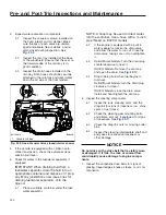
1.
Push the reset button on the dash-mounted air
intake restriction indicator, if equipped.
2.
With the ignition switch in the OFF position,
check the air-pressure warning system.
2.1
If not previously drained, drain the air res-
ervoirs using moderate brake applications
until pressure in both reservoirs is less
than 70 psi (483 kPa).
2.2
Turn the ignition to the ON position. The
ICU will complete a full gauge sweep and
bulb check, and an audible warning will
sound. Ensure the low air pressure lamp
(BRAKE AIR) remains illuminated and an
audible warning continues to sound after
the gauge sweep is complete.
3.
Check air governor cut-in and cut-out pressures.
3.1
Start the engine and ensure the BRAKE
AIR lamp goes out and the buzzer si-
lences when pressure reaches approxi-
mately 70 psi (483 kPa) in both air reser-
voirs.
The air governor should cut out at ap-
proximately 120 psi (827 kPa). For ve-
hicles with an optional dryer reservoir
module (DRM), the cut-out pressure is
approximately 130 psi (896 kPa).
12/15/2014
f462252
1
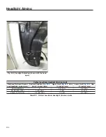
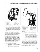
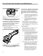
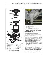
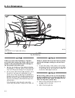
NOTE: Typical reservoir shown; configurations may
vary.
1.
Filler Cap
Fig. 23.5, Power Steering Fluid Reservoir
03/14/2016
f200864
1
2
3
4
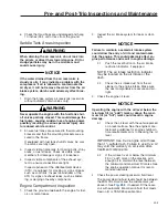
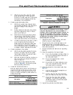
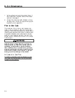
1.
Pressure Relief Cap
2.
Filler Cap
3.
COLD MAX Fill Line
4.
COLD MIN Fill Line
Fig. 23.6, Coolant Surge Tank
Pre- and Post-Trip Inspections and Maintenance
23.5
Summary of Contents for NEW CASCADIA 2016
Page 1: ... NEW CASCADIA Driver s Manual Part Number STI 500 Publication Number STI 500 8 ...
Page 5: ......
Page 11: ......
Page 38: ...f611444 10 31 2016 Fig 3 23 Sample Alert Messages Instruments 3 20 ...
Page 39: ......
Page 93: ......
Page 94: ...8 Cab and Sleeper Features Windows 8 1 Mirrors 8 1 Cab Amenities 8 1 Sleeper Amenities 8 2 ...
Page 99: ......
Page 125: ......
Page 134: ...14 Steering System Power Steering System 14 1 ...
Page 145: ......
Page 146: ...16 Manual Transmissions and Clutch Eaton Fuller Manual Transmissions 16 1 Clutch 16 1 ...
Page 149: ......
Page 150: ...17 Drive Axles Interaxle Lock Tandem Axles 17 1 Driver Controlled Differential Lock DCDL 17 2 ...
Page 164: ...19 Trailer Couplings Holland Trailer Coupling 19 1 ...
Page 177: ......
Page 191: ......
Page 198: ...25 Specifications Fluids and Lubricants 25 1 ...


