

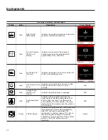


NOTICE
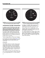
A sudden increase in transmission fluid tempera-
ture that is not caused by a load increase may
indicate mechanical failure. Bring the vehicle to a
safe stop and investigate the cause to prevent
further damage. Do not operate the vehicle until
the cause has been determined and corrected.
Under heavy loads, such as when climbing steep
grades, temperatures that exceed the normal oil tem-
perature range for a short period are not unusual. If
the temperature returns to normal when the load de-
creases, there is no problem.
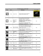
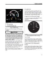
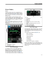
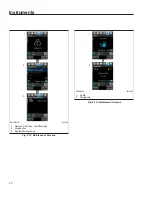
Turbocharger Boost Pressure Gauge
A turbocharger boost pressure gauge (
) indi-
cates the pressure in the intake manifold, in excess
of atmospheric pressure, being created by the
turbocharger.
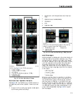
Voltmeter
The voltmeter indicates the vehicle charging system
voltage when the engine is running and the battery
voltage when the engine is off. By monitoring the
voltmeter, the driver can stay aware of potential bat-
tery charging problems and have them fixed before
the batteries discharge enough to create starting diffi-
culties. A digital voltage display is integrated in the
driver display.
The voltmeter will normally show approximately 13.7
to 14.1 volts when the engine is running. The voltage
of a fully charged battery is 12.7 to 12.8 volts when
the engine is off. Battery voltage under 12.0 volts is
considered a low battery, and a completely dis-
charged battery will produce only about 11.0 volts.
If the voltmeter shows an undercharged or over-
charged condition for an extended period, have the
charging system and batteries checked at an autho-
rized Freightliner service facility.
On a vehicle equipped with a battery isolator system,
the voltmeter measures the average voltage of all the
batteries when the engine is running. When the en-
gine is off, the voltmeter shows only the isolated bat-
tery voltage and does not indicate the voltage of the
engine-starting batteries.
f611383
10/31/2016
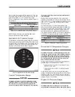
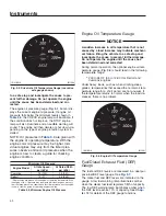
Fig. 3.9, Transmission Fluid Temperature Gauge
f611382
10/31/2016
Fig. 3.10, Turbocharger Boost Pressure Gauge
Instruments
3.11
Summary of Contents for NEW CASCADIA 2016
Page 1: ... NEW CASCADIA Driver s Manual Part Number STI 500 Publication Number STI 500 8 ...
Page 5: ......
Page 11: ......
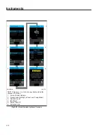
Page 38: ...f611444 10 31 2016 Fig 3 23 Sample Alert Messages Instruments 3 20 ...
Page 39: ......
Page 93: ......
Page 94: ...8 Cab and Sleeper Features Windows 8 1 Mirrors 8 1 Cab Amenities 8 1 Sleeper Amenities 8 2 ...
Page 99: ......
Page 125: ......
Page 134: ...14 Steering System Power Steering System 14 1 ...
Page 145: ......
Page 146: ...16 Manual Transmissions and Clutch Eaton Fuller Manual Transmissions 16 1 Clutch 16 1 ...
Page 149: ......
Page 150: ...17 Drive Axles Interaxle Lock Tandem Axles 17 1 Driver Controlled Differential Lock DCDL 17 2 ...
Page 164: ...19 Trailer Couplings Holland Trailer Coupling 19 1 ...
Page 177: ......
Page 191: ......
Page 198: ...25 Specifications Fluids and Lubricants 25 1 ...


