


RTC Control (RTCC) register assembles main parameters of this module, modifiable fields are:
CNTEN: Counter enable (write ‘1’ for enabled),
RTCIE: RTC interrupts enable (write ‘1’ for enabled),
FRZEN: Freeze enable (write ‘1’ for freezing the module in debug mode),
ROVREN: Counter roll over interrupt/wakeup event enable (write ‘1’ for enabled), when
enabled, if the counter reaches 0xFFFFFFFF and goes back to 0x00000000 an interrupt is
triggered.
RTCVAL: RTC compare value, when bits [21:10] of the counter is matched with this
value, an interrupt is triggered.
APIEN: API module enable (write ‘1’ for enabled),
APIIE: API interrupts enable(write ‘1’ for enabled),
CLKSEL: A 2-bit field for selecting a clock for the counter, 00: SXOSC, 01: SIRC, 10: FIRC,
11: reserved.
DIV512/32EN: Enabling 512/32 divider, these dividers allow to get counter period slow
enough to measure important amounts of time (these dividers should be set before
enabling the counter).
APIVAL: API Compare Value, this is the value of the period for triggering an interrupt.
The minimum value is 4, and its value should be change while API is not enabled. There
will a small transient time in the first period.
The RTC Status (RTCS) register is needed to clear ISR flags; RTCF is for RTC interrupt
generated on match, APIF is for the API interrupt and ROVRF is for the RTC interrupt generated
on roll over.
The last RTC register is the count value (RTCCNT) register it has the 32-bit field RTCCNT
which contains the current value of the RTC counter with maybe up to 6 cycles of delay. The
delay is caused by the clock source difference between system clock and RTC clock but its effects
remain small.
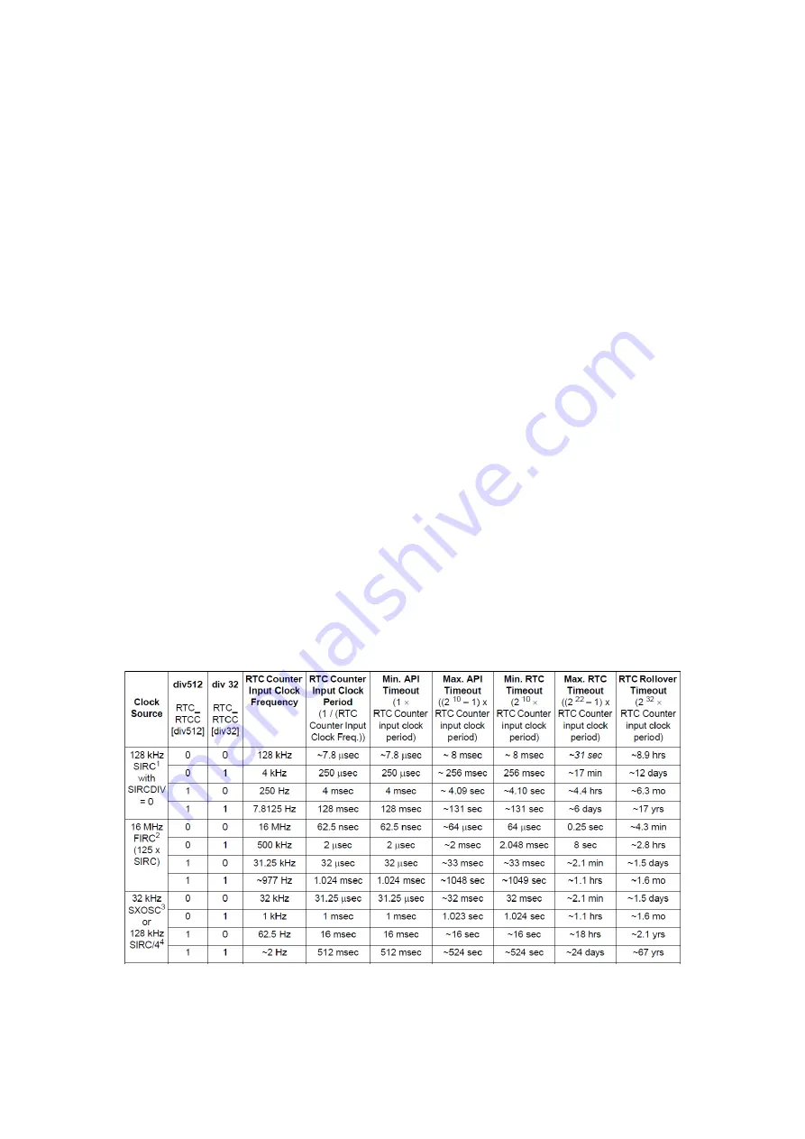
Figure 42 : Different resolutions and timeout limits for RTC/API
Summary of Contents for MPC5604B
Page 1: ...LAAS CNRS Quick Start to MPC5604B Embedded Development Sahin Serdar 21 06 2013...
Page 31: ...Figure 33 INTC SW HW mode comparison Freescale Tutorial...
Page 87: ......
Page 132: ......
Page 133: ...127 Appendix 2 Pad Configurations...
Page 134: ......
Page 135: ......
Page 136: ......
Page 137: ......
Page 138: ......
Page 139: ......
Page 140: ......
Page 141: ...Appendix 3 Peripheral input pin selection...
Page 142: ......
Page 143: ...137 Appendix 4 Interrupt Vector Table...
Page 144: ......
Page 145: ......
Page 146: ......
Page 147: ......
Page 148: ...Appendix 5 I C Baud Rate Prescaler Values...
Page 149: ......
Page 150: ......


