


The two wires on the bus are called SDA (Serial Data Line) and SCL (Serial Clock Line), once a
transmission starts, slave devices synchronise on these signals, START, STOP, Data Change, Data
Capture and ACKnowledge conditions are carefully chosen for avoiding glitches.
START: SCL High, SDA Falling Edge,
STOP: SCL High, SDA Rising Edge,
Data Capture: after SCL Rising Edge,
Data Change: after SCL Falling Edge,
ACK: slave brings SDA to Low for the next
clock pulse,
NACK: slave leaves SDA at High for the next
clock pulse.
All devices have open drain outputs, so the bus lines have to be pulled up with appropriately
sized pull-up resistors (which affects the baud rate). These bring the bus lines to a high value
during idle times and devices communicate by bringing it down to low.
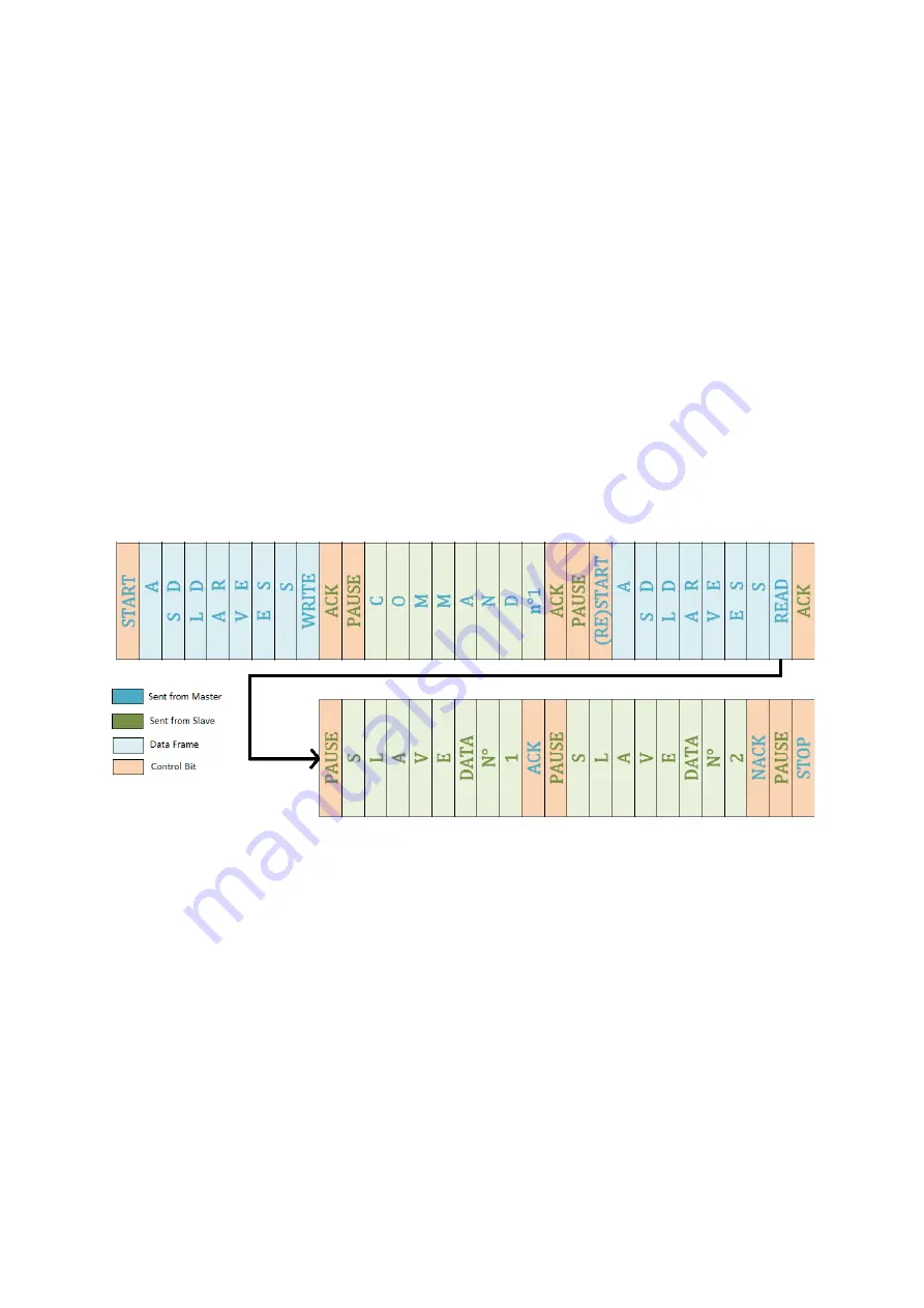
On the figure below, you can see a communication example where the master transmits a
command to the slave and then it proceeds to receive data from it. The master uses NACK signal
to stop the communication. The slave can pause the communication while it executes its
interrupts.
Figure 106 : Communication frames during an I²C transfer
1.2.
Baud rate
There are a few defined standard baud rates for this protocol but other frequencies are allowed.
The baud rate is limited by the pull-up resistor and the bus capacitance. There are four
categories of transmission speed for the bidirectional bus:
Standard-mode: bit-rate up to 100 kbits/s,
Fast-mode: bit-rate up to 400 kbits/s,
Fast-mode Plus: bit-rate up to 1 Mbits/s,
High-speed mode: bit-rate up to 3.4 Mbits/s.
It is harder to establish a bus for high bit rates as the bus capacitance and the pull-up resistor
become more of a problem, sometimes more complex components are needed like current
sources or switched resistor circuits.
Summary of Contents for MPC5604B
Page 1: ...LAAS CNRS Quick Start to MPC5604B Embedded Development Sahin Serdar 21 06 2013...
Page 31: ...Figure 33 INTC SW HW mode comparison Freescale Tutorial...
Page 87: ......
Page 132: ......
Page 133: ...127 Appendix 2 Pad Configurations...
Page 134: ......
Page 135: ......
Page 136: ......
Page 137: ......
Page 138: ......
Page 139: ......
Page 140: ......
Page 141: ...Appendix 3 Peripheral input pin selection...
Page 142: ......
Page 143: ...137 Appendix 4 Interrupt Vector Table...
Page 144: ......
Page 145: ......
Page 146: ......
Page 147: ......
Page 148: ...Appendix 5 I C Baud Rate Prescaler Values...
Page 149: ......
Page 150: ......


