background image

FP S-Compact BB / LAN 

40

Inserting the WiFi stick

Prerequisite

The ISP/WiFi database is configured.

Unscrew the housing cover (see page 19). 

Keep the housing cover and the four screws in a safe place. 

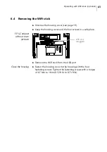
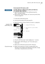
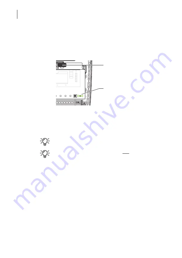
FP S-Compact

without cover

(extract)

Insert the WiFi stick into the USB port.

Wait a few seconds. 

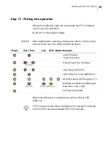
The ‘WiFi’ LED flashes briefly every second. 

The FP S-Compact is now logged on to the router. 
If the ‘WiFi’ LED is not flashing, check the settings, especially the 

password.
Simultaneous use of the LAN interface 

and

 ‘WiFi client’ mode 

on the same network (both wireless and LAN cable connection 

of the FP S-Compact to the WiFi router) is currently not sup-

ported.

Close the housing

Once you have completed setting up the FP S-Compact as a 

WiFi client:

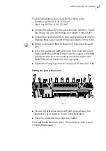
Fasten the housing cover to the housing with the four 

fastening screws. Tighten the fastening screws with a torque 

of 0.7 Nm to 1 Nm (0.52 ft lb to 0.73 ft lb).

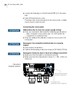
WiFi stick 

(plugged into the USB port)

‘WiFi’ LED

Summary of Contents for FP S-Compact BB

Page 1: ...Installation and Safety FP S Compact BB LAN...

Page 2: ...products FP S Compact C851 LAN 50 0058 1320 00 FP S Compact C851 BB 50 0058 1330 00 FP InovoLabs GmbH Prenzlauer Promenade 28 13089 Berlin Germany Telephone 49 0 30 220 660 601 E mail info inovolabs c...

Page 3: ...r__________________________________________________19 Step 4 Connecting the mobile communications antenna only FP S Compact BB ______________________________________________20 Step 5 Inserting the SIM...

Page 4: ...ta_________________________________________________________________51 11 1 Selected technical data at a glance _____________________________________ 51 11 2 Licenses___________________________________...

Page 5: ...In addition to this guide the following documents among others are available for the FP S Compact devices Datasheet Declaration of conformity Download at https www inovolabs com infobereich downloads...

Page 6: ...roduct documentation for the FP S Compact BB LAN Do not carry out any unauthorised interventions in the hardware and software 2 2 Basic instructions for safe use The device complies with the applicabl...

Page 7: ...ata Ensure that the supply voltage and earthing is connected correctly L N earth compliance with the characteristic values sufficient conductor cross section Any interventions in the hardware and soft...

Page 8: ...sealed with a suitable sealing plug This is the only way to maintain the IP65 protection rating Fasten the housing cover to the housing with the four fastening screws Tighten the screws with a torque...

Page 9: ...rrectly L N earth compliance with the characteristic values sufficient conductor cross section Only carry out a software update if no peripherals are connected Ensure the correct termination of the en...

Page 10: ...vailable at the following internet address https www inovolabs com infobereich downloads handbucher datenblatter Labelling in accordance with the WEEE Directive for electrical and electronic equipment...

Page 11: ...9005 bottom part and RAL D2 000 90 00 cover Built in power supply unit 100 240 V AC CPU 492 MHz ARM Cortex A5 ATMEL SAMA5D27 128 MB RAM 128 MB FLASH Memory USB 2 0 1 1 RS232 1 1 RS485 1 1 Insertion sl...

Page 12: ...urs can also be active at the same time Dat Proc off No process no outbound messages Display of outbound messages Processing Line Mobile communications status display only FP S Compact BB off No cover...

Page 13: ...ict or no IP address received via DHCP Mode Remote Service Serial IP is active WiFi off WiFi not active no USB memory stick loaded flashes briefly WiFi mode active USB memory stick detected and loaded...

Page 14: ...BB LAN 14 3 3 Connection diagram The figure shows the connection diagram for the model FP S Compact BB 1 2 3 4 5 18 17 14 13 16 12 15 6 7 8 9 10 11 25 24 23 22 21 20 19 Protective cover shown here tr...

Page 15: ...connection 230 V L N 11 Connection for protective earth conductor 12 230 V cable gland 13 RS485 connection COM2 14 Cable gland RS485 RS232 15 Cable gland RS485 RS232 16 RS232 connection COM1 17 LAN ca...

Page 16: ...er for ancillary earth 3x sealing plugs for cable glands USB stick with license information Installation and Safety manual this document Important data device type serial number etc that you will requ...

Page 17: ...itable location with good reception the operating software can be used to display the reception quality You can also test the reception quality with a smartphone Notes on signal strength For reliable...

Page 18: ...e device on the wall the serial number plate is no longer visible Use the two fastening screws provided EJOT PT K40x10 WN 1452 Tool T20 and the holes on the back provided for these Rear of the FP S Co...

Page 19: ...ing the FP S Compact 19 Step 3 Removing the cover Loosen the four fastening screws on the cover M3x8 Tool Torx T8 Remove the cover Keep the cover and screws in a safe place Fastening screws for housin...

Page 20: ...the broadband connection Information for the antennae to be used can be obtained from FP InovoLabs We recommend the antenna with article number 90 4771 8002 00 Use an antenna with high antenna gain i...

Page 21: ...into place Damage to the device due to incorrect handling of the SIM card Only insert the SIM card when the device is in a voltage free state Make sure that no SMS messages are stored on the SIM card...

Page 22: ...nd Connect the two cores to the terminals MBus MBus Tighten the clamping screws to a torque of 0 5 Nm 0 37 ft lb The M Bus can be loaded with max 10 M Bus loads and is not galvanically isolated The ca...

Page 23: ...32 COM1 RS485 COM2 Connect the peripheral intended for the application to the RS232 interface COM1 and the RS485 interface COM2 Tighten the clamping screws to a torque of 0 5 Nm 0 37 ft lb RS485 conne...

Page 24: ...se the optionally available WiFi stick order no 90 0072 8100 00 for wireless start up of the FP S Compact FP S Compact acts as an access point Insert the WiFi stick into the USB port After start up th...

Page 25: ...ife when touching live parts Disconnect the cables to which the device is connected from the power supply and secure them against being switched on again Check that the cables to which the device is c...

Page 26: ...pecifications Max conductor cross section size 2 5 mm AWG 14 Copper CU conductors only Only use cables with sufficient conductor cross section for connection Damage to the connection terminals due to...

Page 27: ...yelet M4 to the end of the protective earth wire Screw the protective earth wire onto the connection point marked with the earthing symbol Use the copper screw M4 provided to fasten it on as well as a...

Page 28: ...ugs provided This is the only way to maintain the IP65 protection rating Step 10 Mounting the cover Fit the cover Fasten the cover with the four fastening screws M3x8 Tool Torx T8 Tighten the fastenin...

Page 29: ...indicate the status When the self test is completed the yellow Power LED lights up FP S Compact must still be configured for operation Software tools for this can be purchased from FP InovoLabs Power...

Page 30: ...rning on If it has not received an answer after 30 seconds the device s LAN LED flashes and the default IP address is set as follows Network with DHCP server In a network with DHCP server the host nam...

Page 31: ...delivery and after a factory reset a standard website is installed on the FP S Compact Calling up the standard website Enter the IP address or host name of your device in the address line of your brow...

Page 32: ...f information on the hardware and configuration of your FP S Compact Additionally the configuration can be displayed in a separate window via the System config button and the process data for the conn...

Page 33: ...ction If the FP WLAN Stick FP WiFi stick option has been selected the IP address is already preset and need not be adjusted Now click on the Verbinden Connect button Connection with FP S Compact estab...

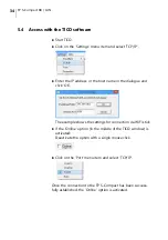
Page 34: ...in the dialogue and click OK The example shows the settings for connection via WiFi stick If the Online option in the middle of the TICO window is activated Deactivate the option with a single mouse c...

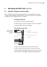
Page 35: ...Inserting the WiFi stick Unscrew the housing cover see page 19 Keep the housing cover and the four screws in a safe place Insert the WiFi stick into the USB port Activating the Access Point FP S Compa...

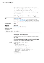
Page 36: ...wing database entries are optional If individual entries are omitted the respective default values apply Example SetConfig _ ISP ver v WLAN_AP SSID _ MySSID EnableOnStartup _ 0 AllowedConnections _ 1...

Page 37: ...Standard WPA2 Password WiFi password ASCII characters no special characters Default value berlin2000 Hostname Host name via which the device can be reached alternative to the IP address Default see SS...

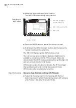
Page 38: ...ection with the FP S Compact Many end devices detect the WPS mode automatically e g Windows 10 and can connect directly to the device WPS mode is active for about 2 minutes The FP S Compact then switc...

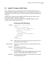
Page 39: ...gured before inserting the WiFi stick Configuring the ISP WiFi database Example SetConfig _ ISP ver y WLAN Profile_0 SSID acer Authentication _ WPA_TKIP Password _ 87654321 Ethernet IP _ DHCP HostName...

Page 40: ...to the router If the WiFi LED is not flashing check the settings especially the password Simultaneous use of the LAN interface and WiFi client mode on the same network both wireless and LAN cable conn...

Page 41: ...sing cover and the four screws in a safe place FP S Compact without cover extract Remove the WiFi stick from the USB port Close the housing Fasten the housing cover to the housing with the four fasten...

Page 42: ...n the FP S Compact Inserting the USB memory stick Disconnect FP S Compact from the power supply The Power LED is OFF Unscrew the housing cover see page 19 Keep the housing cover and the four screws in...

Page 43: ...4 seconds Remove the USB memory stick from the USB port Close the housing Fasten the housing cover to the housing with the four fastening screws Tighten the fastening screws with a torque of 0 7 Nm to...

Page 44: ...ct Press the Service button and keep it pressed Re establish the power supply Wait until the Power LED yellow flashes Release the Service button briefly Press the Service button again Keep it pressed...

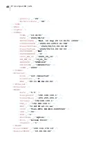
Page 45: ...BB M10 GsmModule _ Huawei ME909s 120 ModuleVer _ 11 617 09 00 00 IMEI _ 123 IMSI _ 123 FlashOnboard _ 128MB COM1 _ RS232 COM2 _ RS485 COM3 _ MBus ETH1 _ ETH1 C14e _ S1 MB10 Modules RAM Size _ 12512870...

Page 46: ...s _ FP S Compact BB RS232 RS485 USB S1 ProdName _ C851 BB M10 LicenseID _ 000100 ProductID _ 3030 UDID _ Tixi com GM20 S1F2K 120 70426 04905322 LicenseRef EEProm LED0 _ 9 EEProm Process VPN Connection...

Page 47: ...alLED _ 9 Mount _ 0 CPULoad _ 92 TixmlQueue _ 1 MB COM1PollActive _ 0 COM2PollActive _ 0 COM3PollActive _ 0 COM4PollActive _ 0 ETHPollActive _ 0 Process LogCounter JobReport _ 3 Event _ 3 Login _ 3 In...

Page 48: ...YY_MM_DD _ 2020_09_16 HH_MM_SS _ 13_41_51 HEXDATE _ 5F62161F UNIXTIME _ 1600263711 YYMM _ 2009 TIMES Ethernet Link _ not connected LinkState _ 0 MAC _ 00 11 E8 8A 24 24 Ethernet Ethernet2 WLAN Rate _...

Page 49: ...d Narrow Band Send SMTP Client CGI DoOn HTTP Server In HTTP Server Out Script Send Express E mail Send Express E mail Recv Incoming Call Auto Transmode Job Result Processor Remote ModemMode SerialNo _...

Page 50: ...o the local network here LTE Long Term Evolution A mobile communications standard SMA SubMiniature Version A high frequency plug connection Antenna connection SSID Service Set Identifier Name of a loc...

Page 51: ...m2 AWG 14 Internal protection with a fuse Power supply conductors Max conductor cross section size 2 5 mm2 AWG 14 Use copper CU conductors only Typical power consumption 12 5 W Prescribed disconnectio...

Page 52: ...t Depending on the transmission rate bus and cable type M Bus via pre installed expansion module S1 MB10 M Bus master for up to 10 M Bus loads Short circuit proof not galvanically isolated M Bus volta...

Page 53: ...s with diversity Quad Band 3G 850 900 1 800 1 900 MHz Quad Band 2G 850 900 1 800 1 900 MHz Data transmission WCDMA CS Downlink 64 kbps Uplink 64 kbps GPRS Downlink 85 6 kbps Uplink 85 6 kbps EDGE Down...

Page 54: ...ial number of the device see serial number plate Example Tixicom C851 BB M10 12345678 Host name for the device FP S Compact BB with the serial number 12345678 SSID Tixi device type SN Device type C851...

Page 55: ...Technical data 55 11 5 General view dimensions Dimensions in mm...

Page 56: ...FP S Compact BB LAN 56 View from above View from below Dimensions in mm...

Page 57: ...ata 57 11 6 Serial number plates FP S Compact BB FP S Compact LAN Space for label with important device data e g device type serial number Space for label with important device data e g device type se...

Page 58: ...FP S Compact BB LAN 58...

Page 59: ...For your notes 59...

Page 60: ...51 0058 9132 01 Rev 01 2021 02 xxx helbig berlin...

Reviews: