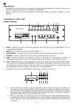
EN
- 4 -
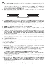
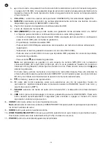
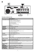
1.-
Z1-Z2-Z3-Z4-Z5-COM
: terminals to connect the loudspeaker lines in zones 1 to 5. In order to activate/
deactivate the zones use the front buttons. With the zone selection terminals only loudspeakers with100
V line transformers must be used. The total connected power in loudspeakers must not exceed the
power of the amplifier. Connect the positive of each zone to the corresponding terminal Z1 to Z5 and
the one common to all zones to the COM terminal.
2.-
VIN
: terminal to make the zones function. If you wish to use the zones outputs, be sure to connect this
terminal to the 100 V or 70 V terminal.
1
2 3
4
5
6
7
8
9 10 11 12
VOL+
VOL-
REC
CLIP
LEVEL
SD/USB
MP3/FM
M3
M4
M2
M1
MEMORY
Z5
Z4
Z3
Z2
Z1
COM
VIN
100 V 70 V COM 16 Ω
8 Ω
4 Ω
COM
3.- Loudspeaker output. For the connection of low impedance loudspeakers 4-8-16 Ω and high impedance
lines of 70-100 V. Connect the loudspeaker line between the COM terminal and the impedance or line
in volts (V) required. Use this loudspeaker output if the zones Z1-Z5 are not going to be connected.
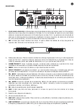
4.-
CHIME PRIORITY
: musical chimes. By closing these contacts the chimes are played if the CHIME
button on the front panel of the amplifier is activated.
5.-
SIREN
: siren. When these contacts are closed the siren signal is played.
6.-
INPUT 1 PRIORITY
: input 1 priority through signal level. Close these contacts to activate priority of
INPUT 1. The rest of the inputs will be attenuated when a signal is detected in INPUT 1.
7.-
TEL. INPUT
: telephone input terminals. Allow the connection of a telephone switchboard to make
announcements from a switchboard with priority over the rest of the inputs. Connect the switchboard
between the amplifier terminals HOT and COM. Consult the characteristics of the switchboard to adjust
it to the input level of the amplifier.
8.-
TEL. LEVEL
: TEL. INPUT volume control. Allows adjustment of the volume of the telephone switchboard
which is connected to the terminals TEL. INPUT. Turning the knob clockwise increases the volume and
anticlockwise, reduces it.
9.-
FM
: FM digital tuner aerial input.
10.-
GND
: screw for earth disconnection, to be used in the case of the plug not having it incorporated.
11.- Power supply voltage selector.
12.- AC power supply socket.
13.-
LINE OUT
: aux line output. To connect an amplifier, mixer, etc., 2 x RCA connectors.
14.-
AMP IN/PRE OUT
: the connection bridge between the 2 RCA connectors communicates the output
signal of the preamp (PRE OUT) with the input of the amplifier (AMP IN).
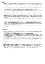
15.-
INPUT 5
: line level inputs which use 2 x RCA connectors and euroblock terminals. Use the DIP
microswitches to adjust the following parameters depending on the characteristics of the signal:
The microswitch 1 (AUX 1/2) allows selection between the two input signals if both are connected.
The microswitch 2 (-10 dB PAD ENABLE) allows attenuation of the input signal in 10 dB.
When the microswitch 3 is activated (HIGH PASS FILTER) a high pass filter is introduced in the signal
path to reduce the low frequency noise.
The microswitch 4 (0 dBu/-10 dBV) allows the input signal level to be adapted depending on the type
of signal introduced.
16.-
INPUT 1-4
: mic./line inputs which use a combo connector (XLR and 6.3 mm jack) and euroblock
terminals. Use the DIP microswitches to adjust the input depending on the characteristics of the signal:
With the microswitch 1 (LINE/MIC (ON)) it is possible to select the sensitivity of the input, for micropho-
ne signal or line level signal.
The microswitch 2 (PHASE) inverts the input signal phase. It is used to avoid cancellations and to co-
rrect phase inversions due to the connection, especially for unbalanced signals.

