


56
Provincial Road n.78 Km 12.150
33050 Mortegliano (UD) – Italy
Tel. +39.(0)432.992482 – +39.(0)432.993557
Fax +39.(0)432.931280
Sito web:
www.flysynthesis.com
e-mail:
Maintenance Manual
FLY SYNTHESIS TEXAN
TOP CLASS 580 ISR
(For Rotax 912 ULS
versions)
Identification: MM_TC_580_Rev.2
Page: 56 of 77
Date: 15/02/11
Issued: C. Cosatto
Verified: C. Cosatto
Approved: C. Cosatto
Revision Description:
Placard update
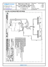
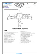
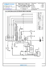
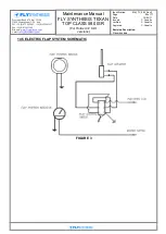
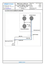
14.1 ELECTRICAL SYSTEM
The electrical system is a 12-14 volt DC system. Electric power is generated by the
generator / alternator, integrated into the engine, and rectified to DC by the rectifier /
regulator that controls the output voltage. Under normal operating conditions, when the
engine is at high RPM and the generator is charging the battery, the system voltage will
be 13.75 to 14 volts.
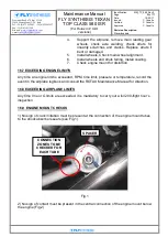
A 12 volts, 18Ah sealed lead acid battery is installed in the engine compartment on the
front left side of the firewall and is constantly charged as long as the engine is running.
The battery will supply electrical power without the alternator for short periods, e.g. use of
landing lights (when installed) and for system connected devices e.g. radio while the
engine is stopped. The engine starter also operates from this battery.
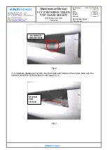
The electrical system is protected by fuses, located near the regulator rectifier above the
battery, in the engine compartment.
The electrical plant is protected by circuit breakers positioned on engine instruments
pannel side. The switches on central instruments pannel have all two positions (ON/OFF).
The connected devices are:
Engine instruments
, Oil pressure and oil temperature indicators, CHT (Cylinder Head
Temperature), RPM (Round Per Minute), EGT (Exhaust Gas Temperature) , fuel quantity
gauges and fuel low-level caution lights. These are fed to the devices when the Master
Switch (key) is the ‗ON‘ position. Also the fuel electric pump and the starter relay are fed
via the master switch when it is in its ‗ON‘ position.
Avionics systems
like radio and navigation receivers when installed are connected via
ON position of the Aux Switch.
The voltmeter
(Optional installation) indicates the electrical system voltage. When
operated on battery only, it should indicate 12 volts. When the engine is running and the
alternator operates it should approximately 14 volts. Under overload conditions the
voltage will drop.
The Master Switch
has two positions: OFF, electric power to the engine and optional
consumers is off. ON, engine instruments are on, and all other electrical devices are
supplied. The Master switch control also flap system.
The Master key have five positions:
-
OFF
, electric power to the engine and optional consumers is off.
-
R
, RH magnet ON.
-
L
, LH magnet ON.
-
BOTH
, both magnets ON.
-
START
, ignition engine ON.
The electric fuel pump
switch has two positions, OFF and ON.