


53
Provincial Road n.78 Km 12.150
33050 Mortegliano (UD) – Italy
Tel. +39.(0)432.992482 – +39.(0)432.993557
Fax +39.(0)432.931280
Sito web:
www.flysynthesis.com
e-mail:
Maintenance Manual
FLY SYNTHESIS TEXAN
TOP CLASS 580 ISR
(For Rotax 912 ULS
versions)
Identification: MM_TC_580_Rev.2
Page: 53 of 77
Date: 15/02/11
Issued: C. Cosatto
Verified: C. Cosatto
Approved: C. Cosatto
Revision Description:
Placard update
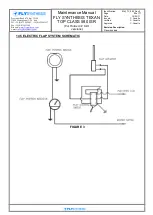
13.1 INSTRUMENTS AND AVIONICS
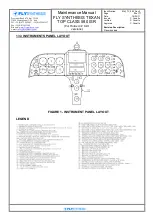
The instrument panel assembly consists of three divided sections, left, centre and right.
The instruments are screw-mounted to the panel. In the normal configuration, the flight
instruments are located on the LHS panel and the engine and system instruments are
located on the RHS panel. The central panel is usually used for radio and GPS
installation.
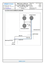
13.2 BASIC MINIMUM FLIGHT AND ENGINE INSTRUMENTS
The basic airplane is delivered with the following minimum flight instruments:
Airspeed indicator, Altimeter, Rate of Climb Indicator, Slip indicator and Magnetic
compass.
The Basic aircraft is delivered with the following engine and system instruments:
Engine RPM (Revolutions Per Minute), CHT (Cylinder Head Temperature), oil pressure,
oil temperature, fuel pressure, fuel quantity (2 indicators per number of fuel tanks), fuel
level low warning light, (2 amber lights), EGT (Exhaust Gas Temperature) indicator and
engine hour meter, generator warning lamp, flap angle indicator, master switch and
magneto switch.
Other approved Avionic apparatus such as Radio, Transponder, Auto Pilots and GPS etc
are listed on the supplementary options list.
APPENDIX C