


48
Provincial Road n.78 Km 12.150
33050 Mortegliano (UD) – Italy
Tel. +39.(0)432.992482 – +39.(0)432.993557
Fax +39.(0)432.931280
Sito web:
www.flysynthesis.com
e-mail:
Maintenance Manual
FLY SYNTHESIS TEXAN
TOP CLASS 580 ISR
(For Rotax 912 ULS
versions)
Identification: MM_TC_580_Rev.2
Page: 48 of 77
Date: 15/02/11
Issued: C. Cosatto
Verified: C. Cosatto
Approved: C. Cosatto
Revision Description:
Placard update
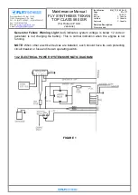
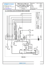
11.1 FUEL SYSTEM OPERATION
Fuel is stored in one or two tanks, installed in the right hand and left hand wing root area.
Two tanks are fitted as standard.
Fuel tank capacity of each tank is 50 litres, out of which 1 litres in each tank is unusable
fuel. Total fuel capacity max is 2x50 litres
– 100 Litres, with 98 litres being usable.
The fuel tank is equipped with a vent line coming from the upper outboard sidewall of the
tank to below the lower surface of the wing. Refilling is through the filler cap on top of the
right and left wings in the standard dual tank configuration.
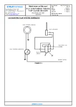
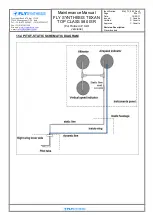
A fuel quantity transducer in the tank transmits the fuel quantity to the fuel quantity
indicator in the cockpit.
A ‗low fuel level‘ switch in the tanks signals when fuel is low to a ―Fuel Low‖ amber caution
light in the cockpit, when only 12 litres of fuel are left per tank.
Fuel can be used only from one tank at a time; it is mandatory to open only one fuel valve
at a time.
Note:
Never open both fuel valves at the same time. If both fuel valves are open and one
tank is empty, it is possible that fuel pump may suck air instead of fuel.
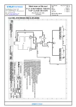
Fuel is drawn from the bottom of the tank through a finger strainer and through a fuel
valve in the cockpit, labelled ON (open) and OFF (closed).
The fuel line passes through the firewall to the engine compartment to the main fuel filter.
The fuel filter is located at the lowest point of the fuel system and is equipped with a drain
valve to enable fuel system drainage of water, should contamination occur. At the filter,
fuel is separated into two parallel lines, one through the mechanical engine driven fuel
pump, and the second line through the auxiliary fuel electric pump. After the pumps, both
lines enter the collector chamber, from which two lines feed the two carburettors; another
line is connected to the mechanical fuel pressure indicator inside the cockpit. A return fuel
line is provided behind a restrictor, and excess fuel is returned.
In normal operation the engine driven pump supplies fuel under pressure. The auxiliary
electric fuel pump is a back up pump in case normal fuel pressure is lost due to engine
pump failure, and it is also used to prime the carburettors before engine start. The electric
fuel pump should always be switched ON for take-off and landing.
- Fuel Valve, two tank system:
ON Left (left open)
OFF right (right closed)
ON Right (right open)
OFF left (left closed)
- Electric fuel pump
ON
OFF
Fuel quantity Indicator (one per tank),
Indicates usable fuel quantity in respective tank
Low level fuel warning light (one per tank)
Indicates fuel level low in respective tank
Fuel pressure indicator
Indicates fuel pressure at the carburettor inlet.