


Fluke 19xC-2x5C
Users Manual
70
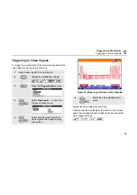
Table 2. F1...F4 Key Functions
Select the Limit Setup function, see page
81.
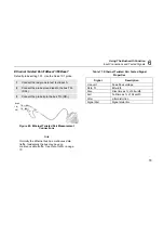
Shows how to connect the test tool to the
bus.
Select the Eye-pattern screen mode, see
Viewing the Bus Waveform Screen on
page 79.
Turn fieldbus test function ON/OFF.
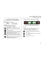
Input Connections and Tested Signals
This section provides a short description of the required
bus connection and the measured signal properties.
See Appendix A for detailed information.
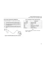
For correct measurements you should calibrate your
probe to match its characteristics to the test tool. A
poorly calibrated probe can introduce measurement
errors. See Chapter 9, section ‘Calibrating the Voltage
Probes’ for calibration instructions.
Data Traffic
In some bus systems (AS-i for instance) the protocol uses
continuous polling of all devices in a fixed time schedule
so that there is continuous data traffic. Other systems
such as RS-232 only carry data when communication is
required. Bushealth requires continuous data traffic to
perform its measurements. In case of very low data
repetition rates, the banner ‘NO DATA’ is displayed. In
systems with low data rates, it is recommended to
increase the data rate by e.g. knob operation. Contact the
system manager for this.
Summary of Contents for 19xC
Page 2: ......
Page 9: ...Contents continued v A Bushealth Measurements A 1...
Page 10: ......
Page 36: ...Fluke 19xC 2x5C Users Manual 26...
Page 60: ...Fluke 19xC 2x5C Users Manual 50...
Page 110: ...Fluke 19xC 2x5 Users Manual 100...
Page 146: ...Appendices Appendix Title Page Bushealth Measurements A 1...
Page 147: ......


