


Fluke 19xC-2x5C
Users Manual
A-2
Used Probes and Accessories
Refer to page 2 and 3 of this manual for an overview of
accessories as supplied with the test tool.
For most bushealth measurements the 10:1 probe(s) are
used. To hook up to bus line nodes you can use the
Alligator Clips or Hook Clips that fit on to the probe tip.
TP88 Back Probe Pins (optional) can be used to probe
screw terminals at the wire entry point.
Important.
For correct measurements you should
calibrate your probe to match its characteristics to the test
tool. A poorly calibrated probe can introduce
measurement errors. See Chapter 9 ‘Calibrating the
Voltage Probes’ for calibration instructions.
You can use the BHT190 test adapter to measure on
busses that use a DB9 or a M12 connector.
Tips and Hints per Bus Type
AS-i bus
The Actuator-Sensor-Interface (AS-i) is used to control
on/off devices at the factory floor. The bus consists of 2
wires and – that carry a 30 Vdc supply with
superimposed data. The AS-i protocol uses continuous
polling of all devices in a fixed time schedule so that there
is continuous data traffic.
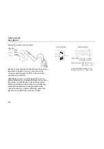
To check AS-i, ScopeMeter Channel A is on and
alternately AC coupled for data or DC coupled to test
30 Vdc. The recommended probe is the Fluke 10:1 probe.
Connect the probe as shown below.
AS-i +
AS-i -
M12 Flat-C
1 Brown
Blue
3
Summary of Contents for 19xC
Page 2: ......
Page 9: ...Contents continued v A Bushealth Measurements A 1...
Page 10: ......
Page 36: ...Fluke 19xC 2x5C Users Manual 26...
Page 60: ...Fluke 19xC 2x5C Users Manual 50...
Page 110: ...Fluke 19xC 2x5 Users Manual 100...
Page 146: ...Appendices Appendix Title Page Bushealth Measurements A 1...
Page 147: ......


