


Fluke 19xC-2x5C
Users Manual
A-4
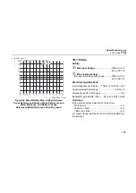
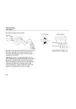
Connect the probes as shown below.
CAN-H
CAN-L
CAN-GND
DB-9
OBD2
6 / 3
7
5 / 5
3
14/11
2
Bus lines can be reached with Back Probe Pins at screw
terminals at a device’s wire entry point: wire colors
commonly used are white for CAN_H, blue for CAN_L,
and black for CAN_GND.
Alternatively you can use a third party DB-9 to 4 mm
banana breakout box. In addition the figure below shows
the pinning of a DB-9 female connector and a typical
Automotive (OBD2) connector. Bear in mind that some
automobile manufacturers leave bus signals at the
connector default on, other manufacturers require bus
signals to be enabled via an external controller.
CAN_H
CAN_L
Ground
1
2
6
3
4
5
7
8
9
DB-9 (FEMALE)
High Speed: HS_CAN_H: Pin 6
Medium Speed: MS_CAN_H: Pin 3
Common (Signal Ground): Pin 5
Battery: Plus: Pin 16 / Minus: Pin 4
9
1
16
OBD2 (FEMALE)
8
HS_CAN_L: Pin 14
MS_CAN_L: Pin 11
Summary of Contents for 19xC
Page 2: ......
Page 9: ...Contents continued v A Bushealth Measurements A 1...
Page 10: ......
Page 36: ...Fluke 19xC 2x5C Users Manual 26...
Page 60: ...Fluke 19xC 2x5C Users Manual 50...
Page 110: ...Fluke 19xC 2x5 Users Manual 100...
Page 146: ...Appendices Appendix Title Page Bushealth Measurements A 1...
Page 147: ......


